Model 6485 and 6487 User’s Manual Connections 2-3
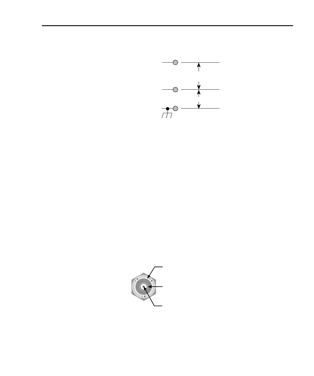
Figure 2-2
Model 6485 maximum input levels
Input HI
Input LO
42V Peak
Chassis Ground
* Maximum Continuous Input Signals
220V Peak, DC to 60Hz sine wave
Max Continuous
Input Signal *
Low noise input cables
When making precision measurements, you should always use low noise cables. As a gen-
eral rule, always use the shortest possible cable for measurements
. See “Model 6485 input
cables, connectors, and adapters,” page 1-4 for recommended cables.
Model 6487 connections
Input connector
The rear panel INPUT connector is a 3-lug female triax connector (Figure 2-3). Make con-
nections using a male terminated triax cable.
Figure 2-3
Model 6487 triax Input connector
Input Low
CAT I
Chassis Ground
Input High