2-14 Connections Model 6485 and 6487 User’s Manual
With Model 6487 front panel operation, an open interlock will display "CLOSE INTLCK"
as an error message when attempting to operate the voltage source on the 50V and 500V
ranges. The Model 6487 in the Model 487 DDC emulation mode displays "IDDCO
ERROR" on the front panel when an "O1" command is sent. The Model 487 displays
"INTERLOCK" for the same condition. The "U9" voltage source error status word func
-
tions the same for either the Model 487 or Model 6487 in DDC emulation mode.
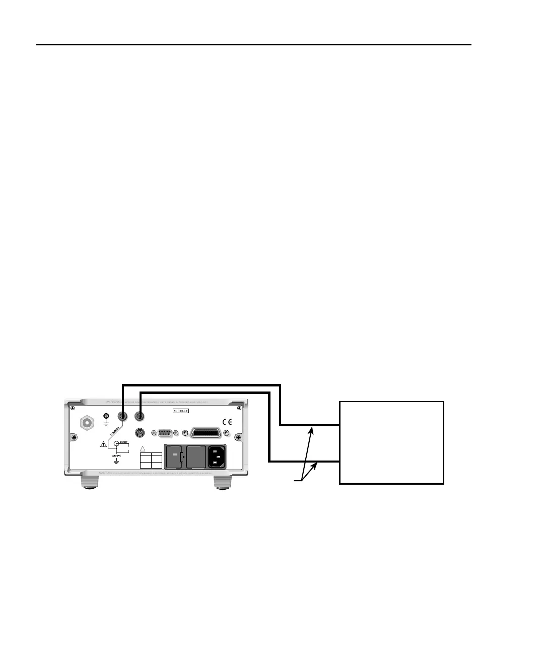
Analog output
The Model 6485/6487 has an analog output on the rear panel. The ANALOG OUT pro-
vides a scaled, inverting ±2V output. A full-scale reading corresponds to ±2V output.
CAUTION Connecting COMMON or ANA
LOG OUT to earth while floating the
input may damage the instrument.
Connections for using this output are shown in Fig
ure 2-14 (Model 6485) and Figure 2-15
(Model 6487). For a full-scale input (i.e. 2mA on the 2mA range), the output will be -2V.
The 2V analo
g output signal is not corrected during calibration. The Model 6485 output
impedance is 1kΩ, while the Model 6487 output impedance is <100Ω. To minimize the
effects of loading, the input impedance of the device connected to the ANALOG OUT
should be as high as possible.
Figure 2-14
Typical Model 6485 analog output connections
120
FUSE LINE
630mA
LINE RATING
50, 60Hz
30 VA
T
(SB)
100 VAC
120 VAC
315mAT
(SB)
220 VAC
240 VAC
!
INPUT
(CHANGE IEEE ADDRESS
WITH FRONT PANEL MENU)
IEEE-488
CAT I
TRIGGER LINK RS-232
MADE IN
U. S.A .
220V PK
ANALOG OUT
Test Lead
Model 6485 Rear Panel
Measuring Device
(i.e. Chart recorder)
LO
HI