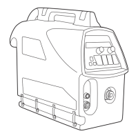
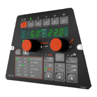
PF65 PANEL OVERVIEW5.12
9. 13.10.11. 12.7.
8.
1. 4.3. 5.
2. 6.
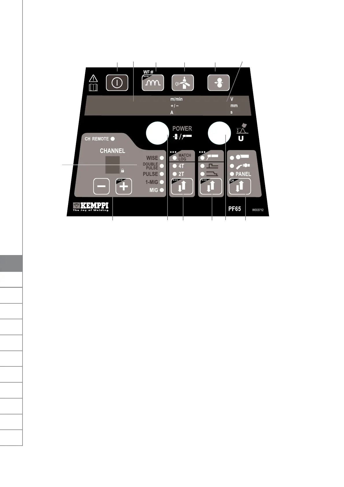
Main switch (long press)1.
a) Wire feed speed/welding current display 2.
b) Display of selected adjustable parameter
a) Activation of MIG welding dynamics / Arc Force adjustment 3.
b) Selection of Wire Feeder (= paralleled wire feeders)
Gas purge 4.
Wire inch 5.
a) Display of welding voltage /plate thickness /timer settings 6.
b) Display of selected adjustable parameter
Selection of MIG gun trigger function: 2T/4T/MATCHLOG long press *)7.
Display of welding process: MIG, 1-MIG, PULSE, DOUBLE PULSE, WISE *)8.
a) Selection of additional MIG functions 9.
b) Activation of MMA welding process (long press*)
a) Adjustment of wire feed speed 10.
b) Adjustment of welding power (Synergic 1-MIG and PULSE)
c) Adjustment of electrode welding (MMA) current *)
d) Adjustment of additional parameters when selected (ie Wire inch, Gas Test)
Memory channels 0-9, programming through P65 panel on the power source, panel lock 11.
(long press on +)
a) Adjustment of welding voltage 12.
b) Adjustment of length of welding arc (Synergic 1-MIG and PULSE)
c) Adjustment of additional parameters when selected (ie MIG Dynamics)
Panel control/remote control unit selection, channel remote control (long press)13.
*) Not included on standard delivery, see chapter 6: Ordering numbers
Automatic Weld Data display:
Last recorded welding values are displayed post welding. See power source panel P65.Select
MENU and then Weld Data.
20
FastMig MXF65, 67 / © Kemppi Oy / 0920
I

 Loading...