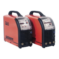
Do you have a question about the Kemppi MLS 2300 ACDC and is the answer not in the manual?
| Brand | Kemppi |
|---|---|
| Model | MLS 2300 ACDC |
| Category | Welding System |
| Language | English |
Adjusts the time taken to reach the set welding current.
Adjusts the time taken to decrease from welding current.
Controls the gas flow duration after welding arc stops.
Controls post-flow gas for MMA welding.
Reduces open circuit voltage in MMA mode for safety.
Defines how downslope is interrupted in 2-stroke mode.
Enables automatic tack welding functionality.
Sets the rate at which welding current increases.
Configures remote controller behavior for TIG/MMA modes.
Sets the initial welding current when the arc starts.
Allows freezing the current at a specific level during downslope.
Configures functions of TIG torch auxiliary switches.
Controls activation of TIG torch auxiliary switches.
Manages the coolant flow control for the machine.
Controls the operation mode of the cooling unit.
Monitors and reacts to coolant temperature changes.
Enables automatic detection of connected remote controllers.
Sets the final welding current level after downslope.
Adjusts the current used for contact ignition.
Sets the duration of the spark ignition process.
Determines the level at which downslope is interrupted.
Resets parameters to factory defaults or empties memory channels.
Controls downslope interruption based on upslope angle.
Adjusts the current drop rate during downslope.
Defines action for a long press of the torch switch.
Sets the duration the cooling unit runs after welding.
Sets the duration for spot welding operations.
Adjusts the arc characteristics for MMA welding.
Controls the pulse during MMA ignition.
Controls the duration of enhanced starting current in 2-stroke mode.
Sets the minimum pre-gas time before welding starts.
Sets the minimum post-gas time after welding ends.
Sets the minimum AC balance for TIG welding.
Sets the maximum pre-gas time before welding starts.
Sets the maximum post-gas time after welding ends.
Sets the maximum AC balance for TIG welding.
Sets the AC frequency for TIG welding.
Selects the AC waveform type for TIG welding.
Adjusts the AC current during half cycles.
Adjusts the AC balance for TIG welding.
Sets the ignition current in the negative half cycle.
Sets the ignition current in the positive half cycle.
Controls the timing of positive ignition current pulses.
Sets the total duration of the ignition cycle.
Defines the cycle time for MIX TIG welding.
Adjusts the pulse ratio for MIX TIG AC welding.
Sets the DC level for MIX TIG welding.
Overview of the machine's operational blocks and their functions.
List and description of error codes displayed by the machine.
Description of operational blocks and components on the main circuit card.
Identification and labeling of connectors on the main circuit card.
Details on the operational blocks and connectors of the PFC card.
Identification of key components on the PFC card.
Description of operational blocks and main components of the secondary rectifier.
Identification and labeling of connectors on the secondary rectifier card.
Description of operational blocks and main components of the secondary inverter.
Identification and labeling of connectors on the secondary inverter card.
Description of operational blocks and connectors on the control card.
Description of operational blocks and connectors on the auxiliary power card.
Description of operational blocks and connectors on the spark card.
Description of operational blocks and connectors on the interface card.
Instructions for performing low voltage and overvoltage tests.
Procedure for testing the power state of the main transformer and secondary rectifier.
Procedure for testing the PFC card functionality.
Procedure for testing secondary overvoltage protection on control/inverter cards.
Instructions for installing semiconductors on the main circuit card Z001.
Instructions for installing semiconductors on the PFC card Z004.
Instructions for installing semiconductors on the secondary rectifier card Z002.
Instructions for installing semiconductors on the secondary inverter card Z003.
