14
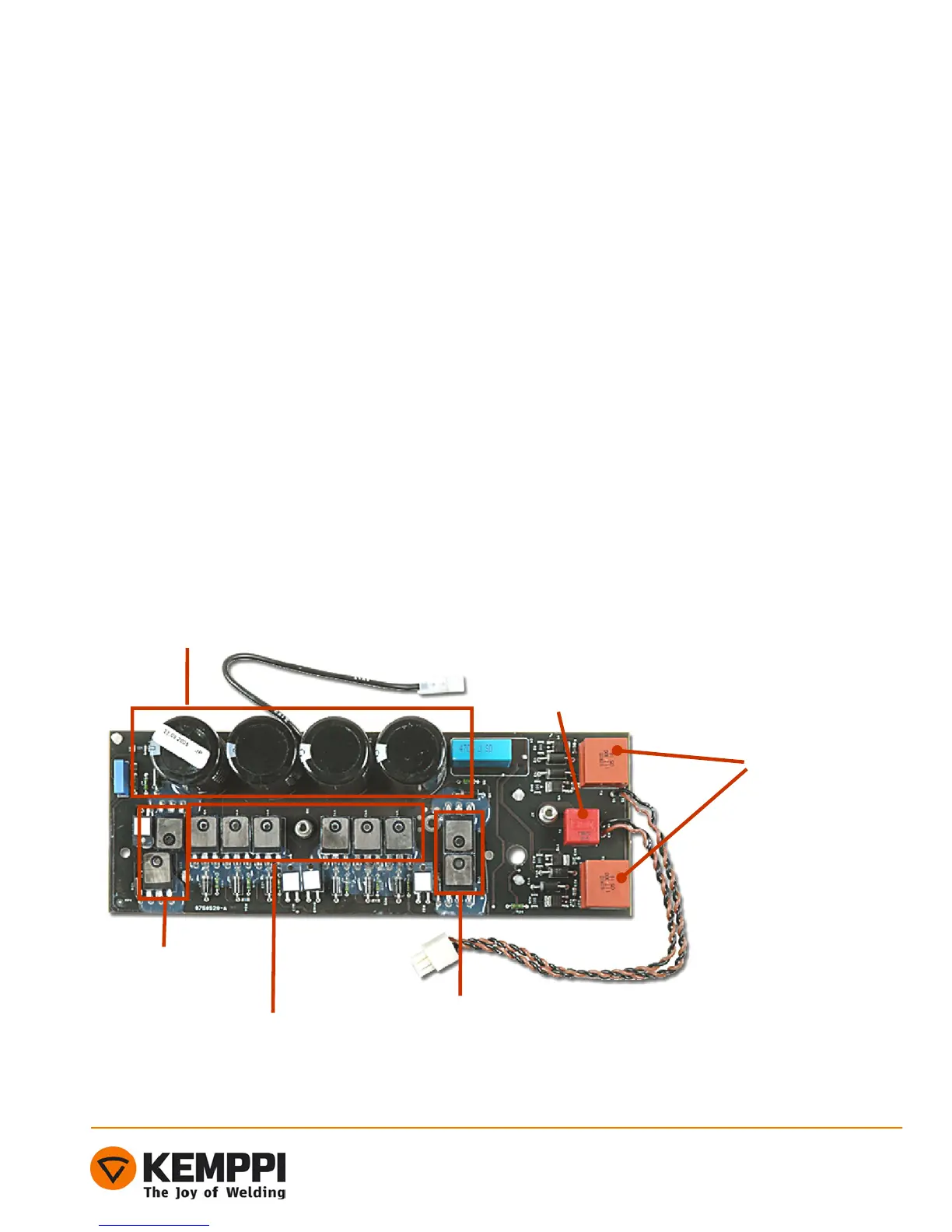
Main circuit card Z001
Functions and components:
Main circuit card Z001 includes following operational blocks:
- Energy reserve
- Power stage (full bridge)
- Damping circuits
- Gate buffers
- Electrolyte capacitors C2, C3, C4 and C5 (470µF/450V) provide the energy storage
- Power stage is a traditional full bridge, where the power switches are parallel connected discrete
IGBTs (30A/600V).
- The current transformer T1 measures the primary current
Note ! IGBTs V12 – V14 and V9 – V11 are insulated from the heat sink!
- Primary inverter's operating frequency is constant, being approx. 65 kHz (cycle time is about 15,3 µs)
throughout the whole power range. Power is controlled by changing the IGBT’s conductivity timings.
Energy reserve
Pulse transformer
Current transformer
Negative half cycle (-) IGBT s
insulated from heat sink !!!
Positive half cycle
(+) IGBT s
Positive half cycle (+) IGBT`s

 Loading...