Man-1112 Sigma XT+_23 Page 13 of 52
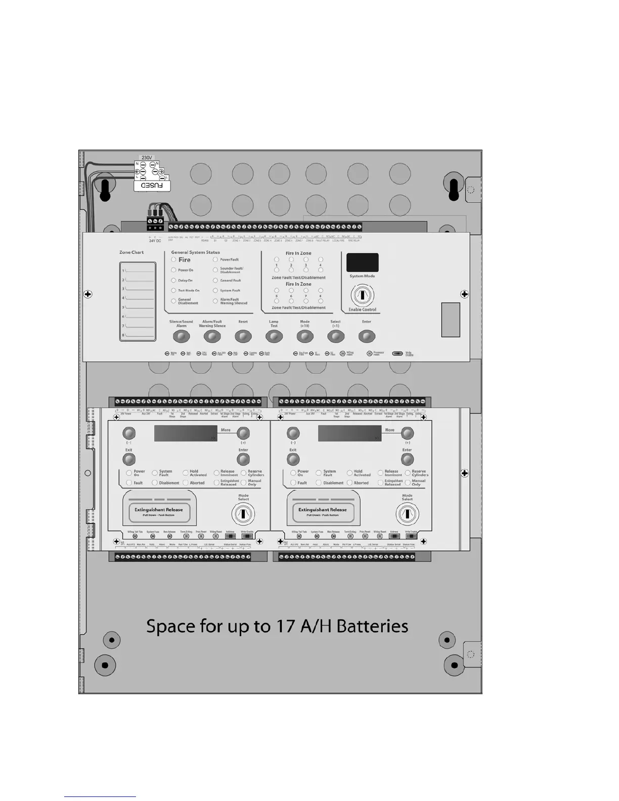
4.1 Removing the fire detection equipment chassis
Open the control panel lid using the two 801 lock keys.
Before the chassis can be removed it will be necessary to disconnect the power connector terminal block on the
left hand side of the PCB. This is fitted on pins and can be pulled towards you to remove it. Do not remove the
wires from the terminals.
The chassis is held in place by two screws. Undo the two screws and lift the chassis gently away from the box
towards you.
With the chassis removed, there is much more room inside the panel for making off and dressing cables.
When cabling work is complete, the chassis can be re-fitted with the two screws and the terminal block plugged
back onto the pins on the board.
The extinguishant module chassis should not be removed.