Man-1112 Sigma XT+_23 Page 20 of 52
10.2 Igniting actuator wiring
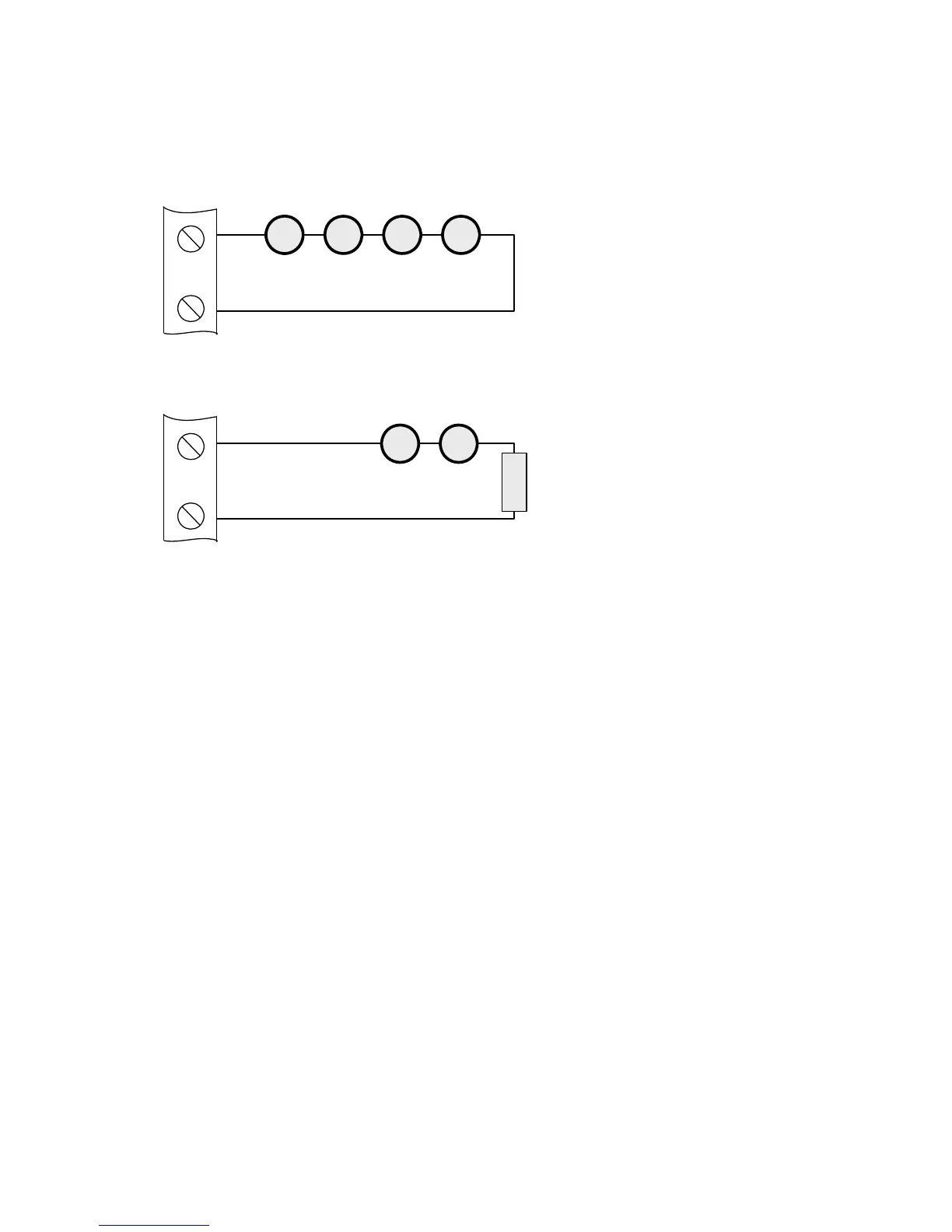
A maximum of four igniting actuators can be wired in series. If only one or two actuators are fitted, a 2R2, 2.5
Watt resistor must be wired in series with them to provide the correct monitoring resistance. The end of line diode
can be discarded when igniting actuators are used.
To guarantee firing under all conditions, the total resistance of actuators, monitoring resistor and cable should not
exceed 7 ohms.
10.3 Setting up extinguishant monitoring circuit
The extinguishing output circuit is factory set to monitor the end of line diode that is fitted to the terminals and
will normally show a value of around 270.
If the parameters of the extinguishant output change e.g. by connecting a solenoid in parallel with the monitoring
diode or removing the diode and fitting igniting actuators, then the extinguishing output monitoring level will need
to be “learnt”. See section 15.2 for details. To do this, operate the enable controls keyswitch to put the system
into access level 2.
The LCD will show:
Access level 2 ►
ENTER for Menu
Operate the WRITE ENABLE switch by gently sliding it to the left. The LCD will show:
AL3 Updates = xx
ENTER for Menu
Press the ENTER button and then the UP button repeatedly until the LCD displays:
Exting. O/P 1
Level = XXX
The XXX displayed here is the previous (factory) level to which the monitoring level had been set.
Press the ENTER button. The LCD will now show:
Exting. O/P 1
Level = XXX ?
The XXX shown here is the current monitoring level detected on the extinguishing output. Press the ENTER button
to learn the new monitoring level.
Press the UP button to set the monitoring level for output 2 in the same way if it is being used, otherwise switch
the write enable slide switch to the right (off) position and check that an open or short circuit fault on the
extinguishing output(s) is detected and shown on the control panel.
+
-
M M M
3 OR 4 ACTUATORS
WIRED IN SERIES
(MAXIMUM OF 4)
EXTING
1 OR 2 ACTUATORS
WIRED IN SERIES
+
-
EXTING
M
M M
FIT 2R2 2.5W RESISTOR
IN SERIES WITH
ACTUATORS IF ONLY 1 OR
2 ACTUATORS ARE USED