Man-1112 Sigma XT+_23 Page 23 of 52
14. Connection and configuration of status units and ancillary boards
The control panel should not be powered during the connection of status units or ancillary boards.
Status units and ancillary boards require a four-wire connection from the associated extinguishing module, which
drops into each unit and connects to the corresponding data and power, in and out terminals. Two of the cables
carry power to the units (24V) and the other two carry data. A four core cable suitable for carrying RS485 data
should be used. If this is a twisted pair cable then one twisted pair should be used for the data connections and
the second pair used for the power connections.
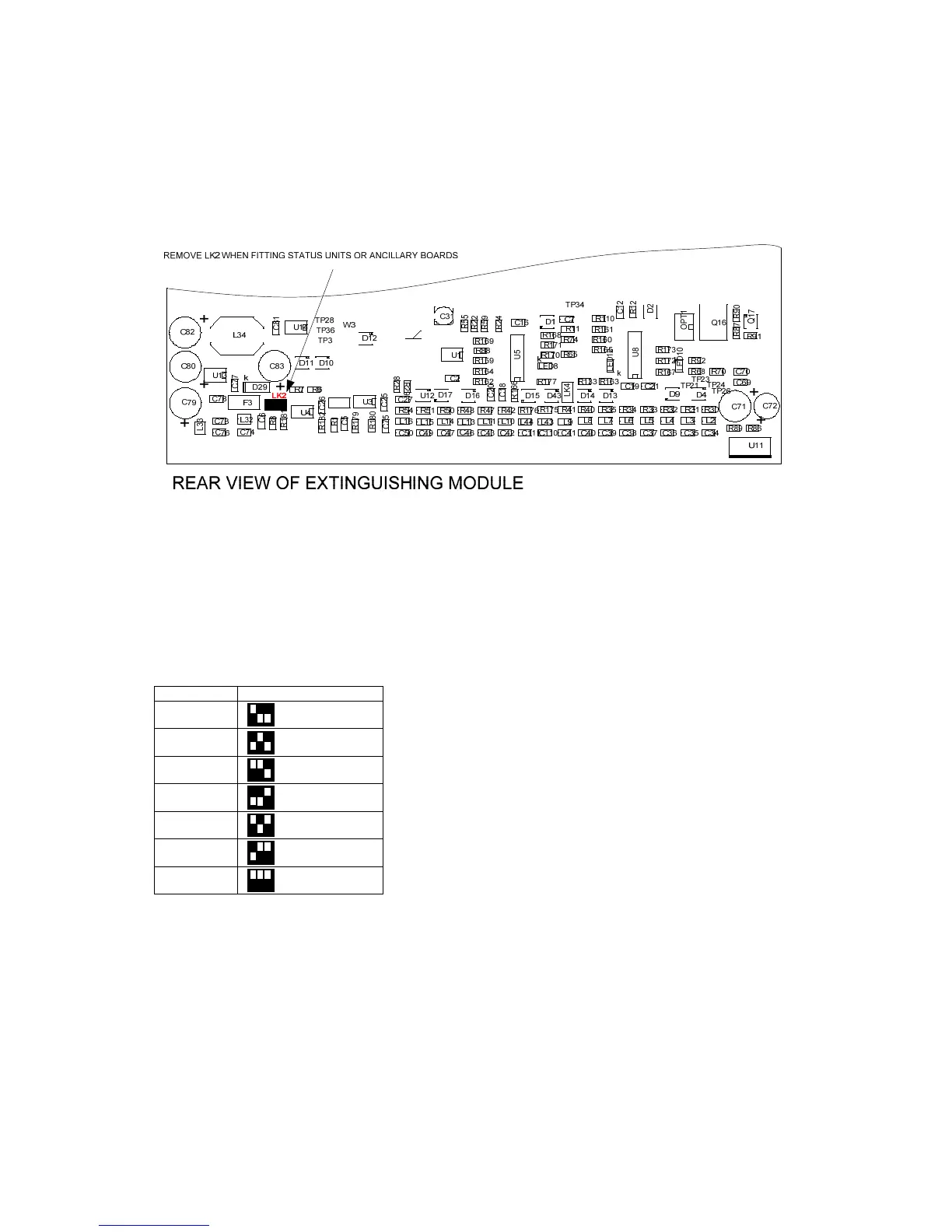
When fitting status or ancillary boards, link LK2 must be removed from the rear of the extinguishant module. The
last status unit connected to the serial bus will have a terminating link fitted as described in manuals MAN-1089
and MAN-1095.
Each status unit and ancillary board has a 3-bit DIL switch and must be allocated a unique address between 1 and
7. A maximum of 3 status units or Ancillary boards can be powered from the extinguishing module 24V output.
More units should use external 24V power supply.
The system is able to distinguish between status units and ancillary boards so it is possible to have a status unit
set to address 1 and an ancillary board set to address 1 if desired.
ADDRESS SWITCH POSITIONS
1
2
3
4
5
6
7
The address switch is located on the bottom left hand corner of the status unit or ancillary board PCB. Note: The
address is only read when the boards are first powered or if the processor reset switch on the ancillary board or
status unit is pressed, so address switches should not be altered on a system that has power applied.
It is important that each individual status unit and ancillary board is allocated a unique address in the range 1 to
7. Units of the same type with the same address will cause intermittent faults to be displayed.
NOTE: 10 lamp status units (models K911113M8, K911113F8 and W911113W8) are not compatible with Sigma
XT+ extinguishant modules.