Man-1112 Sigma XT+_23 Page 17 of 52
6. Detection zone wiring
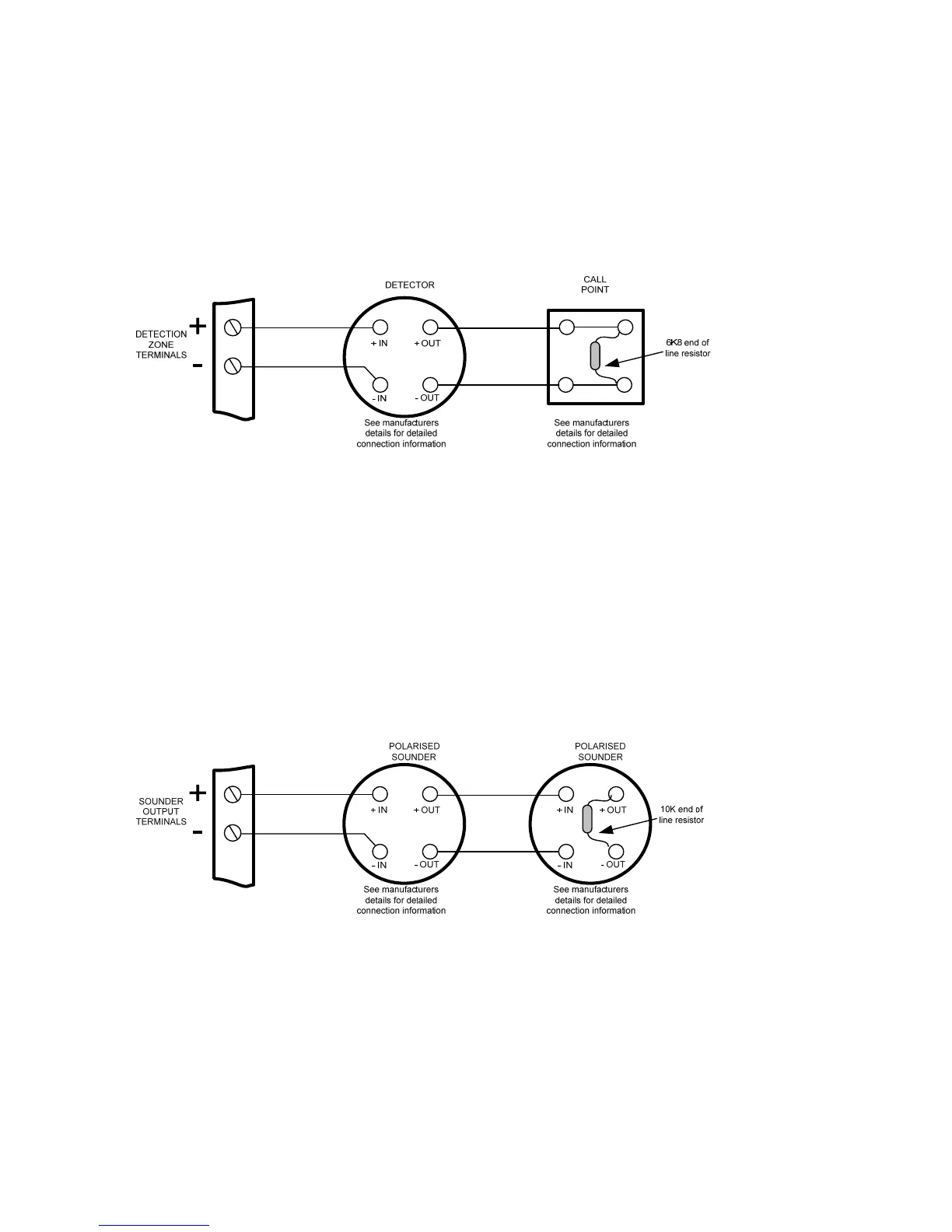
The detection zones provide a nominal 20V DC to power conventional detectors and call points as listed in the
compatibility tables 2 and 3.
The wiring is monitored for open and short circuit fault conditions by removing the 6K8 0.5W end of line
monitoring resistors that are supplied fitted to the control panels’ terminals and placing them across the last
device that is wired to the zone circuit.
Detection zone circuits must be wired as a single, radial circuit with no spurs or T junctions to enable the
monitoring circuit to work correctly.
For systems that are required to comply with BS5839 Part1:2002 detector removal requirements, either detector
bases fitted with a Schottky diode should be used and the end of line resistor replaced with an LCMU active end of
line monitoring device or zener clamping bases such as Hochiki PA6 or Apollo Savwire used.
7. Sounder circuit wiring (alarm devices as required by EN12094-1)
All sounders must be of the polarised type. If non-polarised sounders are used the control panel will permanently
show a fault condition. See table 4 for a list of compatible sounder types.
Sounder circuits are monitored for open and short circuit faults by placing a 10K 0.25W end of line monitoring
resistor across the last device on the circuit.
Sounder circuits must be wired as a single, radial circuit with no spurs or T junctions to enable the monitoring
circuit to work correctly.