Man-1112 Sigma XT+_23 Page 21 of 52
11. Connection to remote control terminals
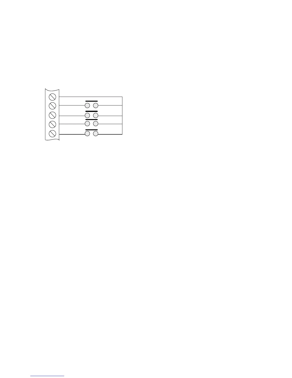
Some functions of the control panel can be controlled externally from the panel if required. The external
equipment operating inputs must be restricted by an access level 2 control as defined in EN54-2 The
functions are abbreviated at the terminals block on the detection zone PCB in the top part of the control panel as
follows:
a) Remote 0 V supply – ROV
b) Silence Alarm – SIL (Silences sounder outputs S1 &S2)
c) Sound Alarm – AL (Operates sounder outputs S1 & S2)
d) Fault – FLT (Generates a general fault and operates the fault relay)
e) Reset – RST (Resets the system back to normal condition)
To activate these inputs, the remote 0 Volt (R0V) supply must be connected to the input via a normally open
switch or contact and via a resistance of no greater than 100 ohms.
All of the remote control inputs are non-latching.
12. Aux 24V DC supply outputs (extinguishant modules only)
The terminals for the Aux 24V supply are labelled Aux 24V + and ROV. The ROV terminal is the negative terminal.
It is possible to have the Aux24V supply outputs removed for a few seconds when the panel is reset.
Aux 24V not removed upon reset is set as default on the extinguishing modules. To change this, switch the system
to access level 2 by operating the enable control keyswitch and then operate the extinguishing module WRITE
ENABLE switch by gently sliding it to the left.
The LCD will show:
AL3 Updates = xx
ENTER for Menu
Press the ENTER button and then the UP button repeatedly until the LCD displays:
R0V Not Removed
On System Reset
Press the ENTER button. The LCD will now show:
R0V Not Removed
On System Reset?
Press the ENTER button. The LCD will now show:
R0V Removed
On System Reset
Press the exit button.
The Aux 24V supply outputs are fitted with an electronic, self resetting fuse rated at 0.5 Amps to protect the
control panel’s 24V supply in the event of a wiring fault. The Aux 24V outputs should not be loaded with any more
than 100milliamps per module.
Any standing load on the Aux 24V supply outputs must be taken into account when calculating battery standby
times as standby time will be significantly affected by even modest standing loads on these outputs. It is
recommended that the Aux24V outputs are not used to power standing loads.
Where the Aux 24V supply outputs are used to power electromechanical devices such as relays or door retainers it
is imperative that a suppression diode is fitted across the coil of the device to prevent the generation of high
voltage transients back to the control panel power supply.
R0V SIL AL FLT RST
SILENCE ALARM INPUT
SOUND ALARM INPUT
RESET INPUT
FAULT INPUT