(20) CII2 INV
Switch
When
the
button
is pushed all the way in, the polarity of the CH2 input
signal
display
will
be inverted.
(21) X-Y
Oscilloscope
Setting
Switch
When
the
button
is pushed
all
the way
in,
ignores
theBJalfflSl
MODE
setting and commences operation as an
X-Y
oscilloscope
with
CHI
as Y-
axis
and
CIT2
as
X-axis.
(22) TRIGGERING!
MODE
selector
switch
For
selecting trigger operation modes.
AUTO
: Sweep is performed by a trigger
signal.
However,
in the absence of a trigger
signal,
free run
will
commence and a trace
will
appear.
NORN
: Sweep is performed by a trigger
signal.
In the absence of
a
suitable trigger
signal,
a trace
will
not
appear.
FIX
Sweep trigger
level
is
fixed.
In this case, triggering
is
made
regardless of
LEVEL
control (25) setting.
TV-FRAME
: Composite video signal
vertical
sync pulses are selected
out and coupled to the trigger
circuit.
TV-LINE
: Composite video signal horizontal sync pulses are select-
ed
out and coupled to the trigger
circuit.
Note : The trigger signal is capacitively coupled to the trigger
circuit
in
this
oscilloscope.
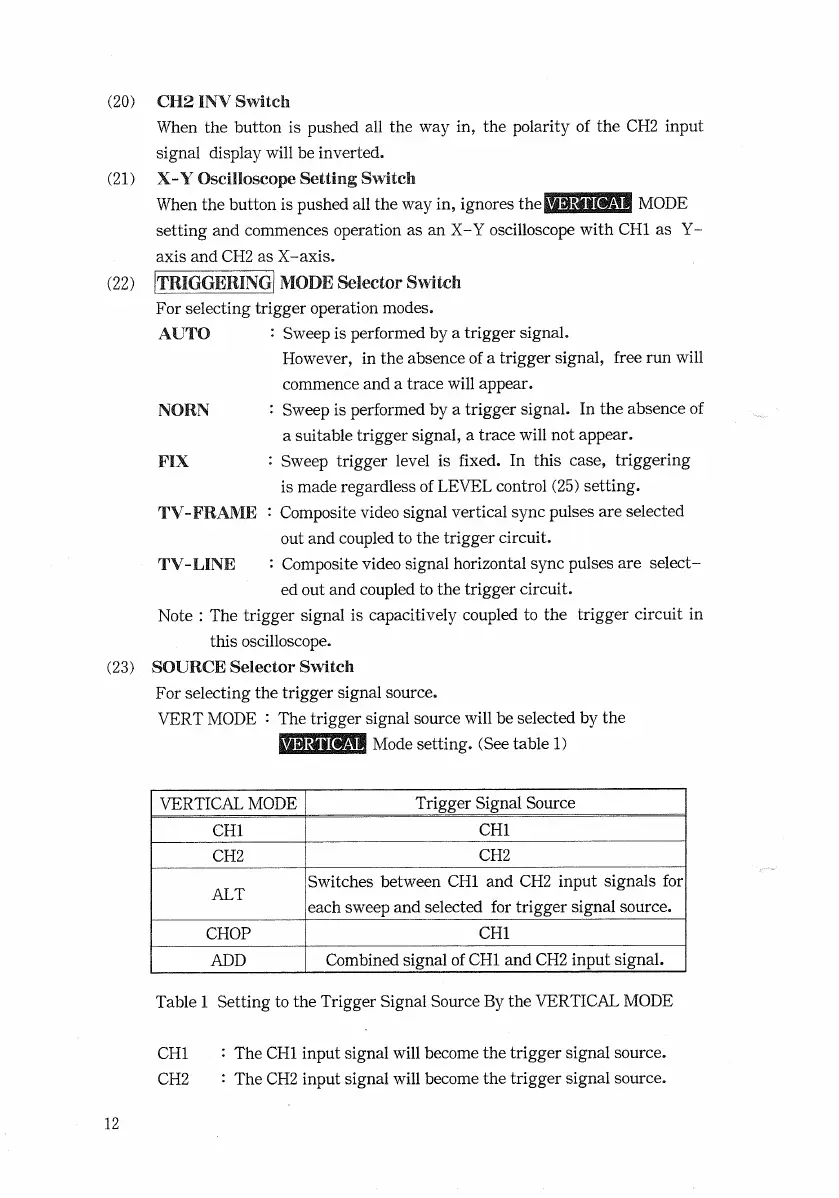
(23) SOURCE
Selector
Switch
For
selecting the trigger signal source.
VERT
MODE
: The trigger signal source
will
be selected by the
Mode setting. (See table 1)
VERTICAL
MODE
Trigger
Signal
Source
CHI
CHI
CH2
CH2
ALT
Switches
between CHI and CH2 input signals for
each
sweep and selected for trigger signal source.
CHOP
CHI
ADD
Combined
signal of
CHI
and
CH2
input
signal.
Table
1 Setting to the Trigger
Signal
Source By the
VERTICAL
MODE
CHI
: The
CHI
input signal
will
become the trigger signal source.
CH2
: The
CH2
input signal
will
become the trigger signal source.
12

 Loading...


