L
R
AUX
IN
SPEAKERS(6–16Ω)
GND
AM
ANTENNA
FM
75Ω
+
-
LR
AG
{
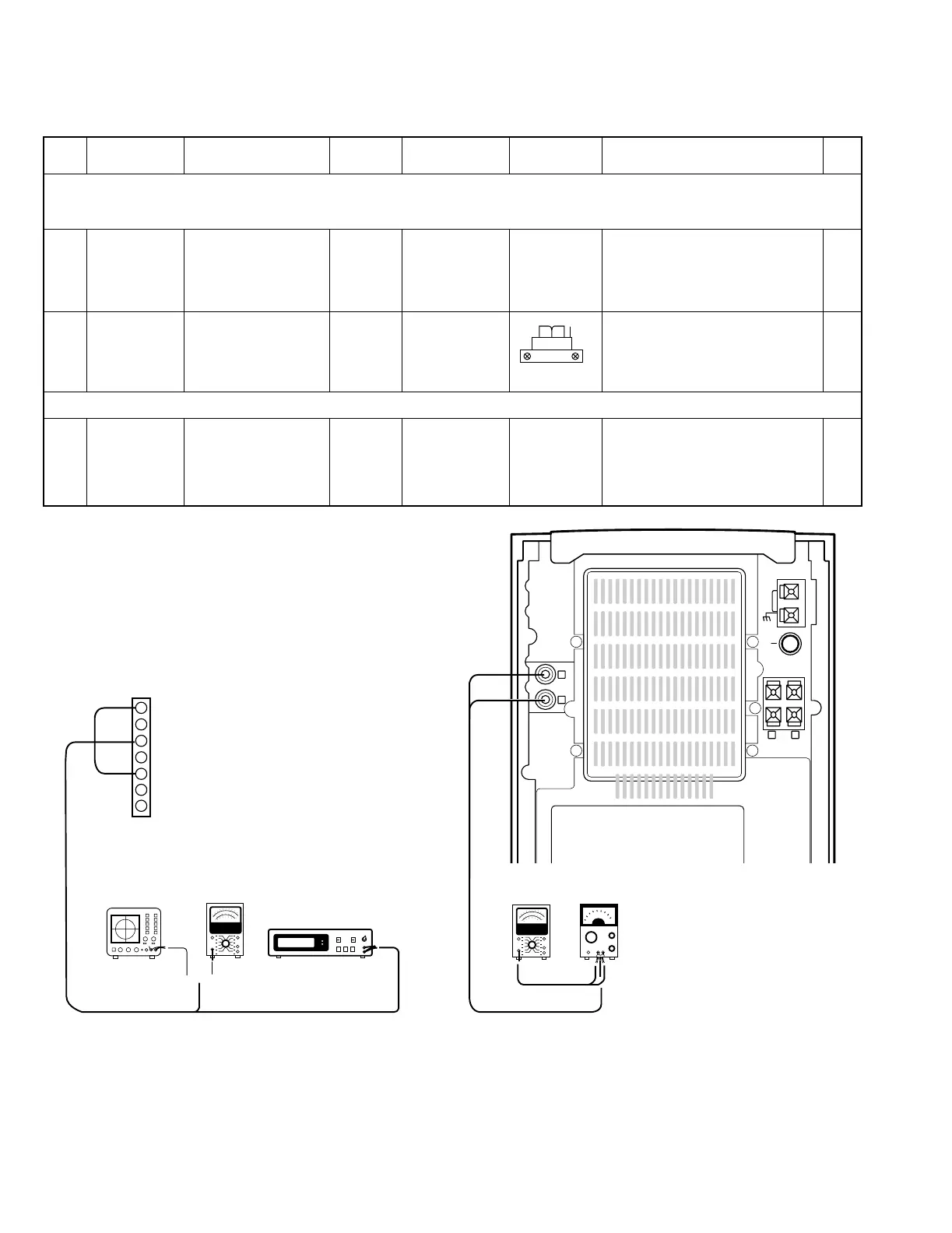
(A)
(B)
Oscilloscope
AC voltmeter AC voltmeter
Frequency counter
X29 CN3
TEST PIN
1
2
3
4
5
6
7
L-PLAY
L-REC
GND
R-REC
R-PLAY
GND
ERASE
RVS FWD
NO. ITEM
INPUT
SETTING
OUTPUT
SETTING
CASSETTE TAPE
DECK SETTING
ALIGNMENT
POINTS
ALIGN FOR FIG.
Unless otherwise specified, set the respective switches as follows: 0dBs = 0.775V
TAPE : NORMAL
I Cassette mechanism unit (Adjustment of the REC / PLAY head)
(1)
Demagnetization
and cleaning
Power : OFF
Demagnetization,
cleaning, PLAY
Recording
head, erase
head, capstan
pinch roller
Demagnetize the REC / PLAY head
with the head eraser. Clean the REC/
PLAY head, erase head, capstan and
pinch roller using a cotton swab slightly
damped with alcohol.
(2)
Azimuth of the
REC / PLAY
head
SCC-1727
TCC-153
MTT-114
10kHz, -10dB
(B) PLAY
Adjust the output to maximum and
adjust the azimuth adjustment screw
for the Lissajours waveform pattern of
the oscilloscope to become close to a
45ß straight ling.
II PC board adjustment.
(1)
BIAS
CURRENT
(A)
Adjust the AG for the
output of the DECK to
become -20dBs
at 12.5kHz/400Hz.
(AC-224)
(B) REC PLAY
VR101(L)
VR102(R)
Record 400Hz and 12.5kHz alternately,
and adjust the bias current adjustment
potentiometer for the playback levels to
become the same.
 Loading...