3
1 INSTALLATION
ACCESSORY CONNECTIONS
FRONT PANEL
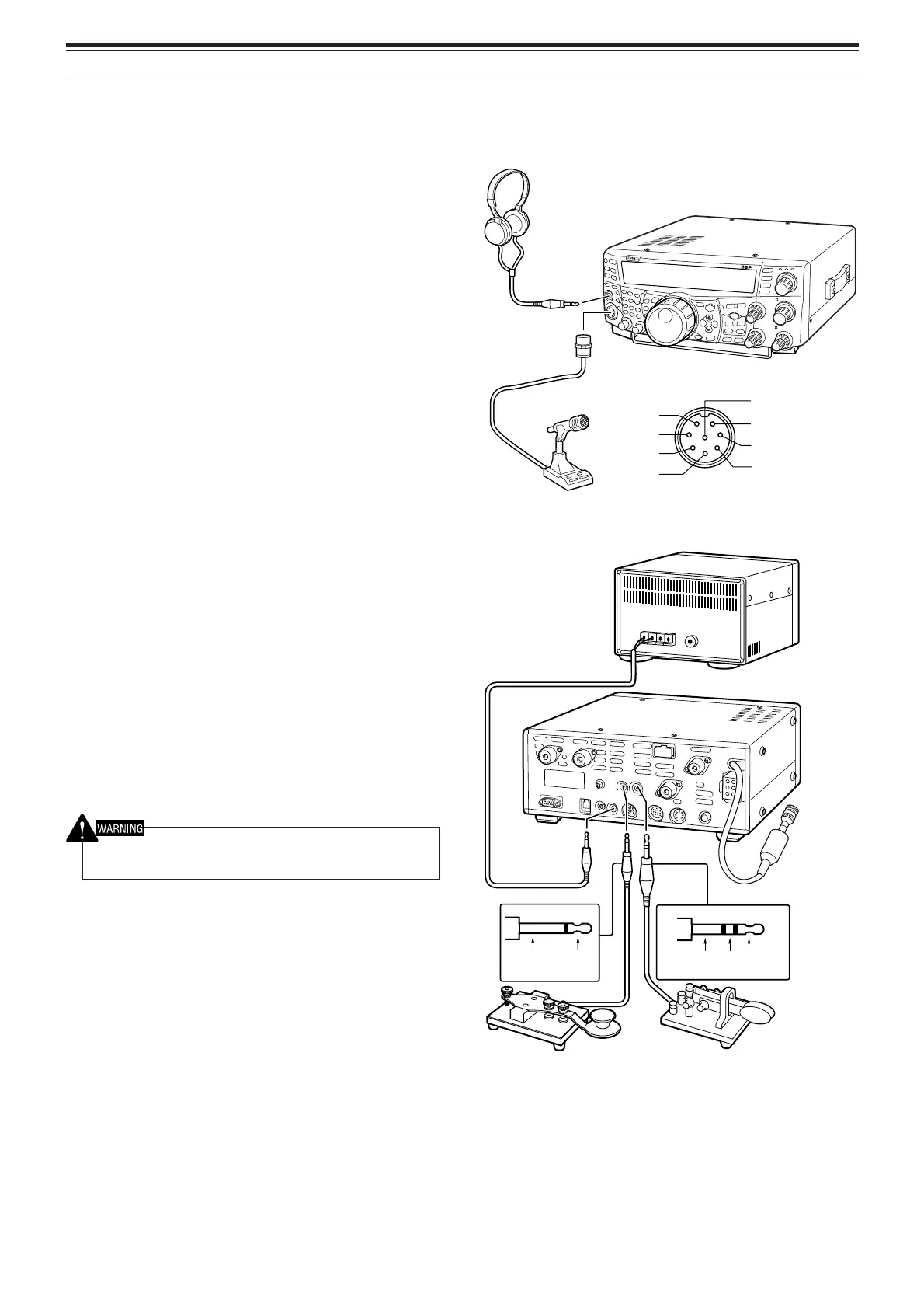
■ Headphones (PHONES)
Connect monaural or stereo headphones having a
4 to 32Ω impedance. This jack accepts a
6.3 mm (1/4") diameter, 2-conductor (mono) or
3-conductor (stereo) plug. After connecting the
headphones, you will hear no sound from the
internal (or optional external) speaker.
■ Microphone (MIC)
Connect a microphone having an impedance
between 250 and 600Ω. Fully insert the
connector, then screw the retaining ring clockwise
until secure. Compatible microphones include the
MC-43S, MC-47, MC-52DM, MC-60A, MC-80,
MC-85, and MC-90. Do not use the MC-44,
MC-44DM, MC-45, MC-45E, MC-45DM,
MC-45DME, and MC-53DM microphones.
REAR PANEL
■ External Speakers (EXT.SP1/ EXT.SP2)
This transceiver has 2 independent receivers.
Thus, it can output 2 separate audio signals. As a
default, the transceiver mixes both audio signals
internally and outputs them from the internal
speaker. On the rear panel of the transceiver,
there are 2 external speaker jacks. If an external
speaker is connected to EXP.SP1, the internal
speaker will mute. If the speaker is connected to
EXT.SP2, both the external speaker and the
internal speaker will function. Use only external
speakers with an impedance of 4 to 8Ω (8Ω
nominal). These jacks accept only 3.5 mm (1/8")
diameter, 2-conductor (mono) plugs.
Do not connect headphones to this jack. The high audio output
of this jack could damage your hearing.
■ Keys for CW (PADDLE and KEY)
For CW operation using the internal electronic
keyer, connect a keyer paddle to the PADDLE
jack. For CW operation without using the internal
electronic keyer, connect a straight key,
semi-automatic key (bug), electronic keyer, or the
CW keyed output from a Multimode
Communications Processor (MCP) to the KEY
jack. The PADDLE and KEY jacks mate with a
6.3 mm (1/4") 3-conductor plug and a 3.5 mm
(1/8") 2-conductor plug respectively. External
electronic keyers or MCPs must use positive
keying to be compatible with this transceiver. Use
a shielded cable between the key and the
transceiver.
Note: Due to the functionality of the internal electronic keyer, you
may find it unnecessary to connect both a paddle and another
type of keyer unless you want to use a PC-based keyer for CW.
Read the “ELECTRONIC KEYER” section {page 42} to become
familiar with the internal keyer.
i
q
u
y
t
w
e
r
TS-2000
TS-2000X
TS-B2000
+
• Straight key • Paddle
• Bug key
• Electronic keyer
• MCP CW output
GND
GND dash dot
Microphone
Headphone
TS-2000
TS-2000X
TS-B2000
MIC connector (Front view)
GND (STBY)
GND (MIC)
NC
8 V (10 mA max)
MIC
PTT
DOWN
UP
External speaker
 Loading...