Annex page 2 of 7
Annex to Test Certificate No. DK0199-R76-11.04
Issued by DELTA
•
Indication of zero
• Semi-automatic subtractive tare
• Acting upon significant fault
• Weighing unstable samples
• Real time clock (optional)
3. Technical data
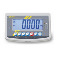
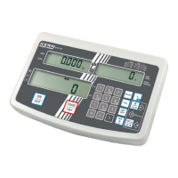
3.1 Indicator
Type KFN-TM / KFB-TM
Accuracy class III or IIII
Weighing range Single-interval, multi-interval or multi-range
Maximum number of verification scale intervals (n) 6000 for single-interval
2×3000 for multi-interval and multi-range,
however limited to 1000 for Class IIII
Minimum input voltage per VSI 1 µV
Maximum capacity of interval or range (Max
i
): n
i
× e
i
Verification scale interval, e
i
= Max
i
/ n
i
Initial zero-setting range: ± 10 % of Max
Maximum tare effect: 100 % of Max
Fractional factor (pi) 0.5
Excitation voltage 5 VDC
Circuit for remote sense Active, (see below)
Minimum input impedance 87 ohm
Maximum input impedance 1600 ohm
Connecting cable to load cell(s): See Section 3.1.1
Supply voltage: 9 - 12 VDC
230 VAC using external Vac/2Vdc adapter
Operating temperature range Min / Max = -10 °C / +40 °C
Peripheral interface(s) See Section 4
3.1.1 Connecting cable between the indicator and the junction box for load cell(s),
if any
3.1.1.1 4-wire system
Line 4 wires, shielded
Maximum length The certified length of the load cell cable, which shall be con-
nected directly to the indicator.
3.1.1.2 6-wire system
Line 6 wires, shielded
Maximum length 227 m/mm
2
Maximum resistance per wire 3.8 ohm