42 / 180
Installation
2017/11
3.3 Fitting the inlet and outlet
Preparation
Risk of functional problems due to suspended matter and solids
deposited on the level sensor.
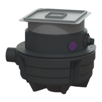
If the inlet is to be at the muffs <26B > or <26C>, the respective
muff must be sawn off at the given cutting edge.
If the inlet to the system tank is to be via position <26C>, the level
sensor <27> has to be exchanged with the cover of the service
opening <30> . To do so, proceed as described below
• Unscrew each of the 4 fastening screws <1> and dismantle the
two assemblies accordingly. Position the anti-twist protection
device <2> correctly
The inlet can be mounted at various positions on the system tank:
24 DN 80
26A
DN 50 or DN 100
26B DN 100
26C DN 100
26D
Scoring surface, maximal DN 100. Make sure that no
backwater enters the inlet pipe
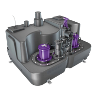
Installing the inlet
• Dismantle the level sensor if necessary
• Mount the inlet on the system tank
Installing the outlet
• Connect the pressure pipe to the connection <24>.
26C
30
27
1
2
Ill. [7]
26A
26D
26C
26B
27
30
24
Ill. [8]