Verification and Adjustments 2
Keysight E36200 Series Service Guide 63
7 Operate the electronic load in constant current mode and set its current to the
value described in Table 2-4.
Set the transient level to ½ the maximum current. Set the transient duty cycle
to 50% and transient frequency to 1 kHz. Check that the front panel CV
annunciator of the power supply remains lit. If it turns to CC or UNREG, adjust
the maximum current load so that the output current drops slightly until the
CV annunciator lights up.
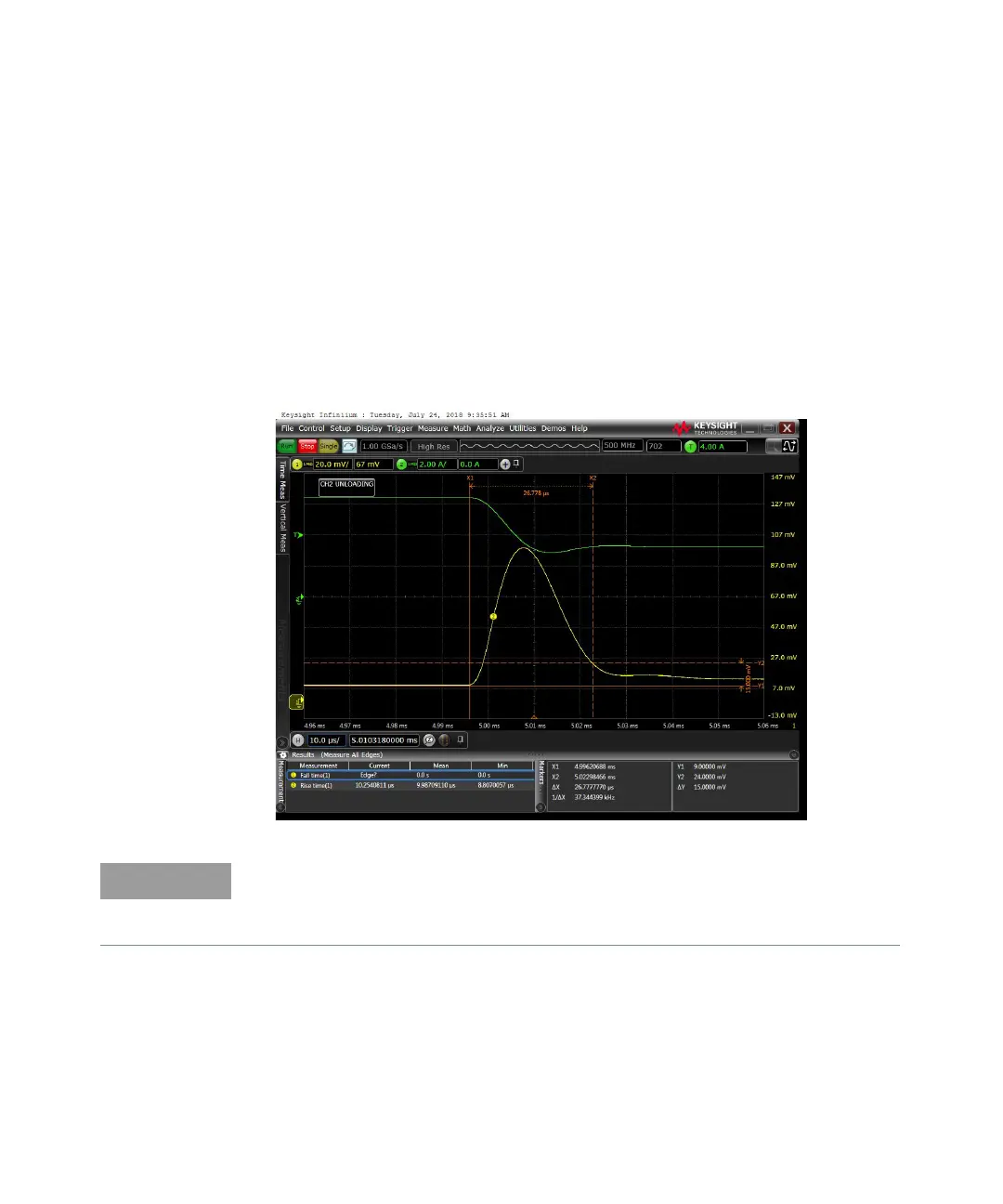
8 Adjust the oscilloscope to display transients as shown below. Note that the
pulse width (t2 – t1) of the transient at the voltage settling band, for example
15 mV for the E36234A Output 1 from the base line is no more than 50 µs.
Record the measured value in the “Test Record Forms” on page 74. The
transient response specification is met when the voltage recovers within
50 µs.
– The oscilloscope cursors X1 and X2 represent t1 and t2.
– The oscilloscope green trace and yellow trace represent output current and
output voltage trace.