Keysight N9927-90001 User’s Guide 201
SA (Spectrum Analyzer) Mode
Channel Measurements
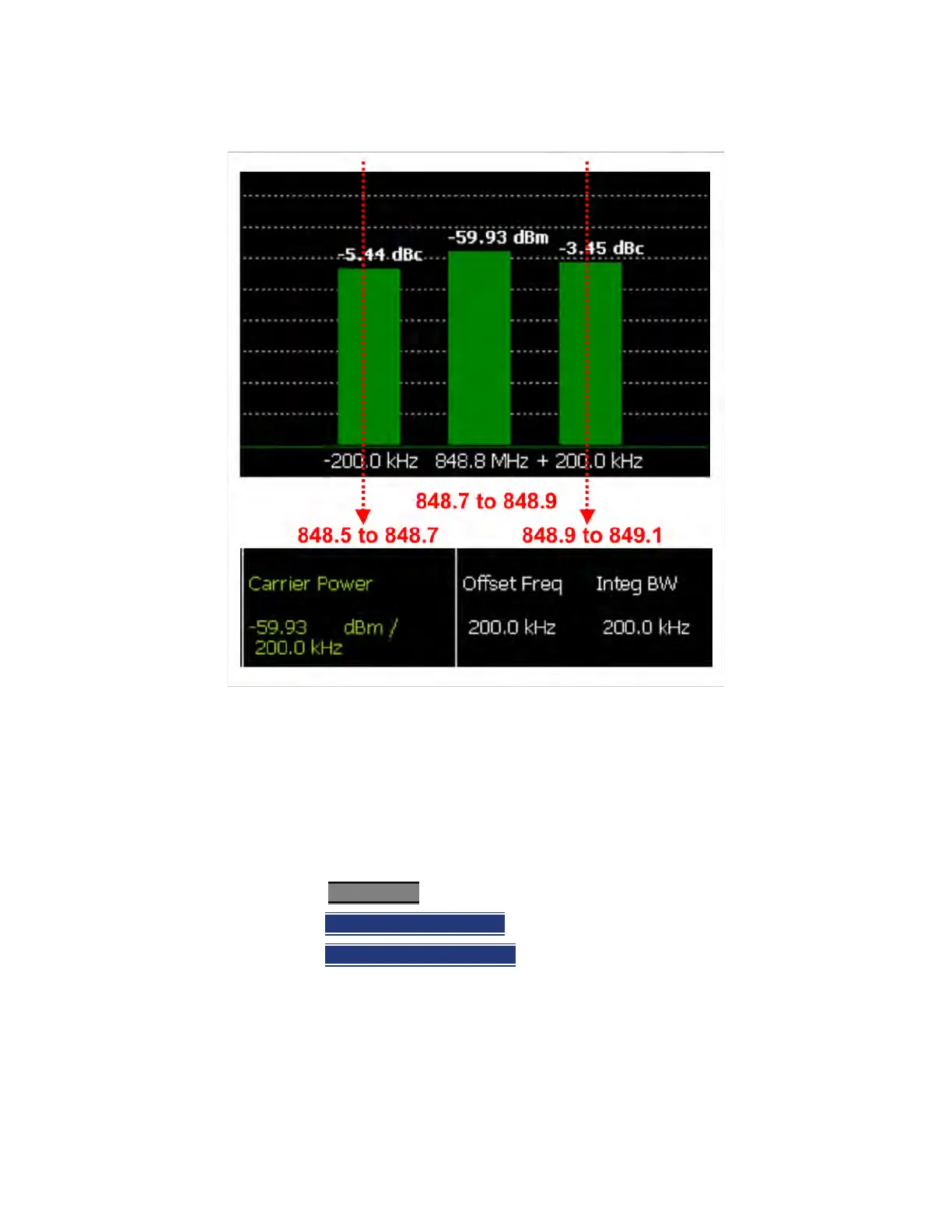
Figure 9-11 GSM 850-Ch 251-Up with one Offset
In the graphic above, red frequencies (MHz) are added to illustrate offset and
integ BW.
Data in the ACPR graphical chart is always presented in dBm for the carrier,
and dBc (dB below the carrier) for the offsets. This can NOT be changed. Use
the Meas Type setting (next page) to change how the data is presented in the
table below the graph.
How to select ACPR
—Press Measure__1
—Then Channel Measurements
—Then Adjacent Channel Power
When ACPR is selected, the following settings are maintained from a previous
measurement: Center Frequency, Preamp ON|OFF, and RF Attenuation.

 Loading...