Base Matrix Configuration 2
Keysight 34934A User’s Guide 173
34934C-001 D-Sub Connectors: Wiring for 8x64
Safety Interlock Continuity
While wiring to the 34934C-002’s D-Sub
connectors, you must
make the following connections—in addition to the 8x64
row and column connections—to provide for safety interlock continuity:
Short: Pin 59 (IL3) to Pin 77 (IL4) on Bank 1
Short: Pin 40 (IL2) to Pin 61 (IL1) on Bank 2
Configuring an 8x64 Matrix by Direct Wiring
34934A module D-Sub Connectors: 8x64 Pin Assignments
The D-Sub connector pin assignments for the 34934C-001 configuration block
mirror those shown for the 34934A module. However—for safety reasons—the
D-Sub pin assignments for the 34934C-002 configuration block do not mirror
those for the 34934A module. Please consult the correct configuration sections
for wiring to the D-Sub connectors.
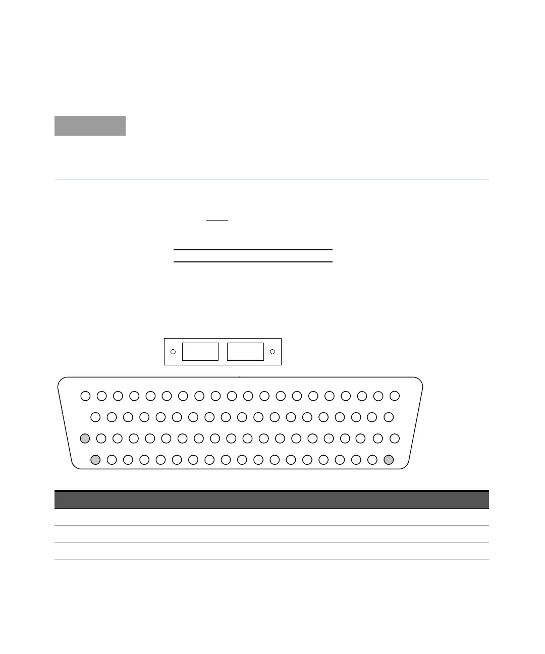
For orientation, the D-sub connector
end of the module is facing you.
Bank 2
Bank 1
78-Pin D-Sub
Male Connector
Bank 1
R1C5 C37 C1 C33 C6 C38 C39 C3 C35 C8 C40 C4 C36C7C2 C34 R1 R2R2
1 2 3 4 5 6 7 8 9 1011 1213 1415 16 17
18
19
20
21
22 23
24 25
26
27
28 29
30 31
32 33 34 35
36
37
39
40
41
42 43
44
45 46
47
48
49 50 51
52
53 54 55
56
57 5958
60
61 62
63 64
65
66
67 68
69 70
71 72 73 74
75
76
77 78
NC C27 C59 C28 C60 C29 C61 C30
C31
C62 C26 C58
R3C15 C47 C9 C41 C16 C48 C43 C12 C44 C13 C45 C14 C46C11C10 C42 R3 ID(2)
R4C21 C53 C22 C54 C23 C55 C56 C18 C50 C19 C51 C20 C52C24C17 C49 R4 IL3NC
C25 C57 C32 C64
IL4 NC
C63
38
Description Pin Description Pin Description Pin Description Pin Description Pin Description Pin
R1 17 C1 3 C17 47 C33 4 C49 48 No connect 40
R1 18 C2 7 C18 51 C34 8 C50 52 No connect 60
R2 19 C3 11 C19 53 C35 12 C51 54 No connect 78