Expanded-Row Matrix Configuration 3
Keysight 34934A User’s Guide 219
In the previous examples, note the module interconnection wires (illustrated from
the side view) which link the configuration blocks. From a side view, although
there are two extension connectors on each side edge (left and right) of each
configuration block; only one is shown.
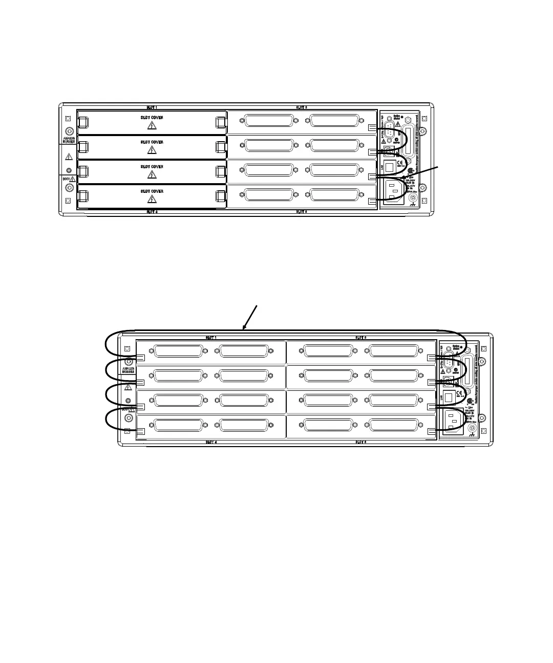
Four 34934A modules (with attached configuration blocks) connected in an
extended-row configuration.
Example: base configuration for each is 16x32; resulting expanded-row matrix is 16x128.
Module
Inter-
Connections
Eight 34934A modules (with attached configuration blocks) connected in an
extended-row configuration.
Example: base configuration for each is 8x64; resulting expanded-row matrix is 8x512.
Module
Inter-Connections