Base Matrix Configuration 2
Keysight 34934A User’s Guide 59
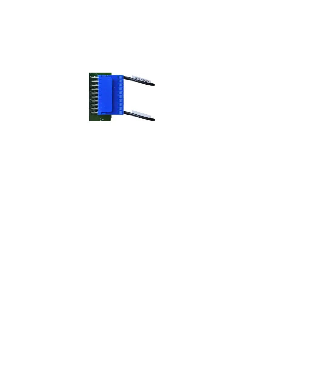
– For each of these headers, install one of the supplied keyed 20-pin terminators
securely in that header, as shown below.
The supplied terminators incorporate both the shorting jumper for pins 19 and
20 and a jumper precluding connection to pins 1 and 2.
– The extension headers on the opposite (unused) side of the 34934C-001 do
not require a safety interlock terminator; these will be hidden by the
configuration block’s cover.
34934C-001 Configuration Block: Wiring
The next two subsections outline options for making row and column wiring
connections to the configuration block.
Extension Header (Row Signal) Wiring to the 34934C-001
Below is an illustration of the possible locations for making row signal connections
to the 34934T-001