Base Matrix Configuration 2
Keysight 34934A User’s Guide 75
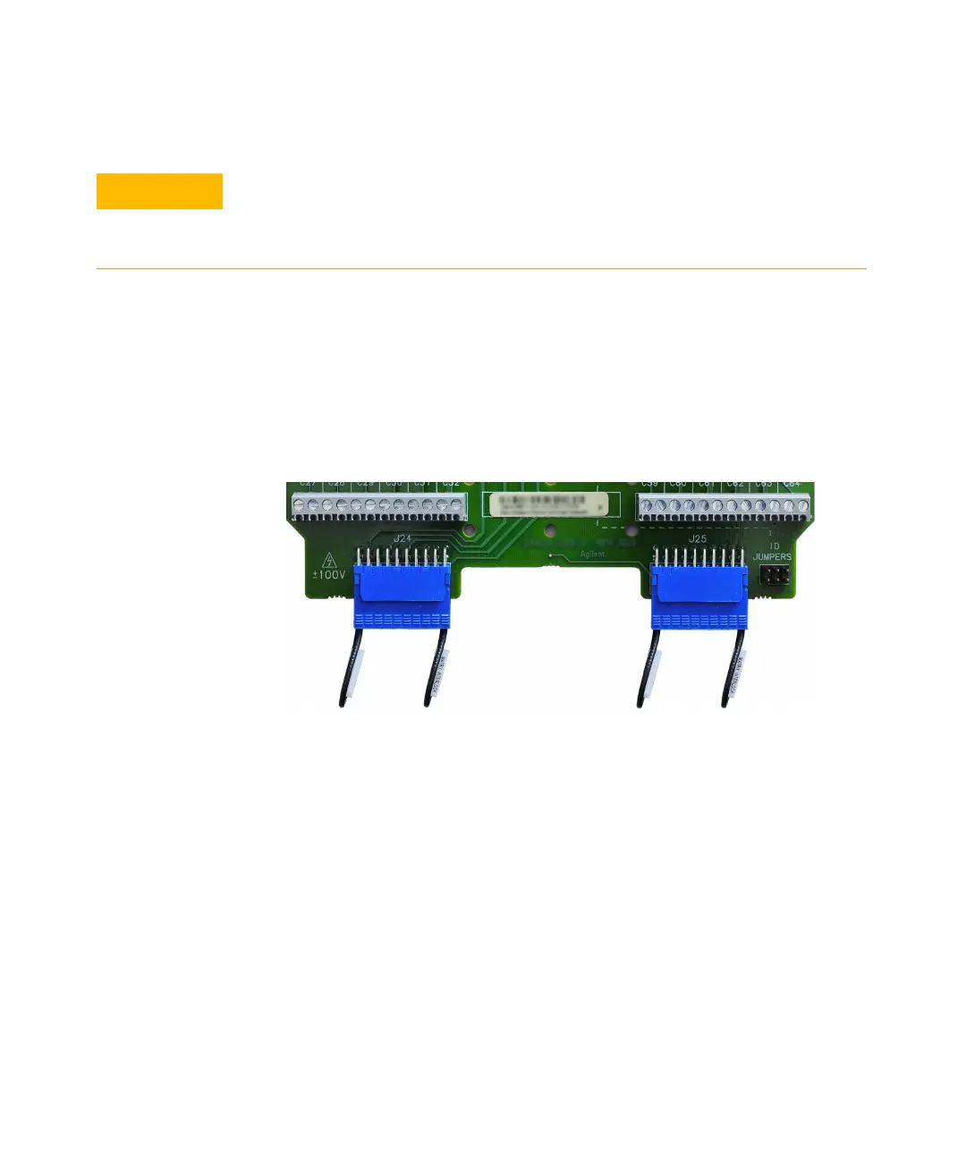
Placing Safety Interlock Continuity Jumpers for 4x64
At the bottom (end
opposite the D-Sub connectors) of the terminal block are two 20-pin extension
headers—marked J24 and J25 on the circuit board. These headers provide access
to the module’s rows. Pins 19 and 20 on each header must be shorted to provide
continuity for the module’s safety interlock function.
Two keyed 20-pin terminators are supplied for providing safety interlock
continuity. Install the terminators securely in the headers, as shown below.
The supplied terminators incorporate both the shorting jumper for pins 19 and 20
and a jumper precluding connection to pins 1 and 2. Detailed pin diagrams for
these terminators are provided on page 78.
34934T-001 Terminal Block: 4x64 Wiring
Once the required jumpers have been placed to configure the terminal block as
4x64, you are ready to make row and column connections to the terminal block.
You may connect to the module’s rows and columns by wiring to the screw
terminals marked C1 through C64 (H, L) and R1 through R4 (H, L) on the
silk-screen. The combined weight of these wires can create significant strain on
the wiring; to minimize this see “Terminal block strain relief” on page 71.
The ID jumpers MUST correspond to the matrix configuration set by the
CONFIG jumpers in the previous step. The instrument firmware functions
based on the ID it detects from the (ID) jumper positions and assumes the
CONFIG jumpers are set accordingly.