2 Calibration Procedures
58 Keysight DAQ970A/DAQ973A Service Guide
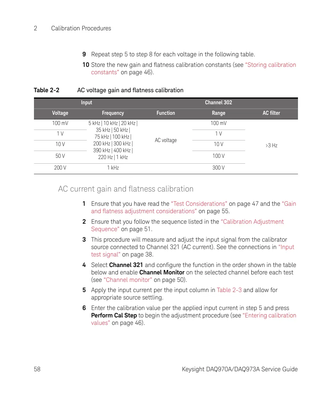
9 Repeat step 5 to step 8 for each voltage in the following table.
10 Store the new gain and flatness calibration constants (see “Storing calibration
constants” on page 46).
AC current gain and flatness calibration
1 Ensure that you have read the “Test Considerations” on page 47 and the “Gain
and flatness adjustment considerations” on page 55.
2 Ensure that you follow the sequence listed in the “Calibration Adjustment
Sequence” on page 51.
3 This procedure will measure and adjust the input signal from the calibrator
source connected to Channel 321 (AC current). See the connections in “Input
test signal” on page 38.
4 Select Channel 321 and configure the function in the order shown in the table
below and enable Channel Monitor on the selected channel before each test
(see “Channel monitor” on page 50).
5 Apply the input current per the input column in Table 2-3 and allow for
appropriate source settling.
6 Enter the calibration value per the applied input current in step 5 and press
Perform Cal Step to begin the adjustment procedure (see “Entering calibration
values” on page 46).
Table 2-2 AC voltage gain and flatness calibration
Input Channel 302
Voltage Frequency Function Range AC filter
100 mV 5 kHz | 10 kHz | 20 kHz |
35 kHz | 50 kHz |
75 kHz | 100 kHz |
200 kHz | 300 kHz |
390 kHz | 400 kHz |
220 Hz | 1 kHz
AC voltage
100 mV
>3 Hz
1 V 1 V
10 V 10 V
50 V 100 V
200 V 1 kHz 300 V