Performance Verification 3
Keysight DAQ970A/DAQ973A Service Guide 73
Frequency accuracy verification
1 Ensure that you have read the “Test Considerations” on page 47.
2 This procedure will measure the input signal from the function/arbitrary
waveform generator connected to Channel 302 (frequency). See the
connections in “Input test signal” on page 38.
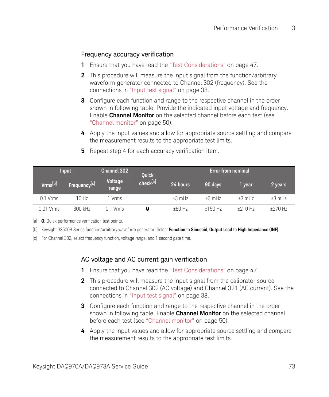
3 Configure each function and range to the respective channel in the order
shown in following table. Provide the indicated input voltage and frequency.
Enable Channel Monitor on the selected channel before each test (see
“Channel monitor” on page 50).
4 Apply the input values and allow for appropriate source settling and compare
the measurement results to the appropriate test limits.
5 Repeat step 4 for each accuracy verification item.
AC voltage and AC current gain verification
1 Ensure that you have read the “Test Considerations” on page 47.
2 This procedure will measure the input signal from the calibrator source
connected to Channel 302 (AC voltage) and Channel 321 (AC current). See the
connections in “Input test signal” on page 38.
3 Configure each function and range to the respective channel in the order
shown in following table. Enable Channel Monitor on the selected channel
before each test (see “Channel monitor” on page 50).
4 Apply the input values and allow for appropriate source settling and compare
the measurement results to the appropriate test limits.
Input Channel 302
Quick
check
[a]
Error from nominal
Vrms
[b]
Frequency
[c]
Voltage
range
24 hours 90 days 1 year 2 years
0.1 Vrms 10 Hz 1 Vrms ±3 mHz ±3 mHz ±3 mHz ±3 mHz
0.01 Vrms 300 kHz 0.1 Vrms Q ±60 Hz ±150 Hz ±210 Hz ±270 Hz
[a] Q: Quick performance verification test points.
[b] Keysight 33500B Series function/arbitrary waveform generator: Select Function to Sinusoid, Output Load to High Impedance (INF).
[c] For Channel 302, select frequency function, voltage range, and 1 second gate time.