Keysight M8000 Series of BER Test Solutions Installation Guide 47
Installing Modules 2
3 Locate the module insertion/extraction handles at both ends of the
instrument module. Extend the ends of both handles, by pulling them
inwards towards each other. Then fully open the handles by pivoting
them out towards you.
4 Align the module’s PCA board with the guide rails on both ends of the
M9505A/M9506A AXIe chassis.
5 Push the module into the chassis slot until the leading edges of the
insertion/extraction latches rest against the front surface of the
chassis. The insertion/extraction latch handles should be
perpendicular to the front surface of the chassis (aligned with the
direction of module insertion). Nudge the module gently inward to
allow the latches to engage.
6 Using your thumbs, press inward firmly on the insertion/extraction
handles until the module is seated firmly in the chassis backplane. The
module front panel should lie flush with the chassis front panel.
7 Push the handles ends towards the edge of the chassis to tuck them
away.
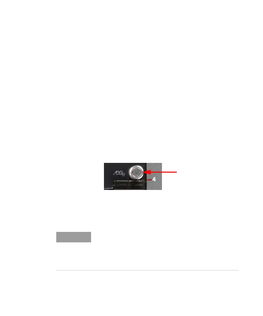
8 Tighten the retaining screws on either end of the module to ensure the
ground connection.
Figure 31 Tighten retaining screws
After you have installed the module in the chassis, ensure that remaining
slots have filler panel modules installed.
Do not operate the chassis without filler panels in empty slots. This is
especially important for the slots on either side of the instrument
module. This allows proper air flow and cooling, and provides EMI
shielding for the chassis and installed components. Leaving slots empty
can increase fan speed, raise ambient noise, overheat components, and
can cause the module to shut down.
 Loading...

