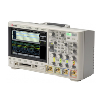
Do you have a question about the Keysight MSOX3054T and is the answer not in the manual?
Details on power requirements and ventilation for safe operation.
Instructions for connecting oscilloscope probes to the channel BNC connectors.
Procedure to match probe input capacitance to oscilloscope channel for accurate measurements.
Adjusts the time/div setting using the horizontal scale knob.
Adjusts the horizontal delay (position) knob to move the trigger point.
Sets the vertical scale (volts/division) for the channel using the large knob.
Configures search parameters to find frequency peaks in FFT math functions.
Adjusts the vertical scale and offset of the math waveform.
Saves the current waveform to one of two reference locations.
Instructions for connecting digital probes to the device under test.
Sets the threshold voltage level for digital channels.
Information on available hardware-accelerated serial decode options.
Using the Search key to find and mark specific data rows in the Lister.
Adjusts the intensity of displayed waveforms for signal detail.
Configures display persistence (Off, Infinite, or Variable).
Adjusts the vertical level for analog channel edge detection using the Trigger Level knob.
Causes a trigger and displays the acquisition, useful when triggers are not occurring.
Identifies a trigger by specified edge (slope) and voltage level on a waveform.
Triggers on a positive or negative pulse of a specified width.
Identifies a trigger condition by looking for a specified pattern (logical AND of channels).
Triggers on any selected line of the video signal.
Evaluates acquisitions based on waveform intersection with defined rectangular zones.
Selects the trigger mode: Auto (default) or Normal.
Selects DC, AC, or LF Reject coupling for the trigger path.
Sets the time the oscilloscope waits after a trigger before re-arming.
Uses Run/Stop and Single keys to control acquisition.
Chooses acquisition modes like Normal, Peak Detect, Averaging, High Resolution.
Divides memory into segments to capture multiple infrequent trigger events.
Uses horizontal and vertical markers to measure voltage, time, phase, or ratio.
Displays the Measurement Menu to add automatic measurements.
Details on voltage measurement points like Peak-Peak, Maximum, and Amplitude.
Explains time measurements like Period, Frequency, Rise Time, and Fall Time.
Defines vertical levels for measurements on analog channels or math waveforms.
Displays statistics like mean, min, max, standard deviation, and count.
Creates a mask based on a golden waveform for compliance verification.
Configures options for running mask tests, including termination conditions.
Provides 3-digit voltage measurements on analog channels.
Measures frequency, period, or edge events (totalize) on analog channels.
Configures and starts the frequency response analysis sweep.
| Bandwidth | 500 MHz |
|---|---|
| Sample Rate (analog) | 5 GSa/s |
| Sample Rate (digital) | 1 GSa/s |
| Memory Depth (digital) | 1 Mpts |
| Form Factor | Benchtop |
| Vertical Resolution | 8 bits |
| Memory Depth (analog) | 4 Mpts |
| Waveform Update Rate | 1, 000, 000 wfms/s |
| Input Impedance | 1 MΩ |
| Maximum Input Voltage | 300 Vrms |
| Trigger Types | Edge, Pulse Width, Pattern |
| Interface | USB, LAN, GPIB, HDMI |
| Operating Temperature | 0°C to +50 °C |
| Channels | 4 analog, 16 digital (with optional logic analyzer) |


