CXPI Triggering and Serial Decode 26
Keysight InfiniiVision 3000T X-Series Oscilloscopes User's Guide 423
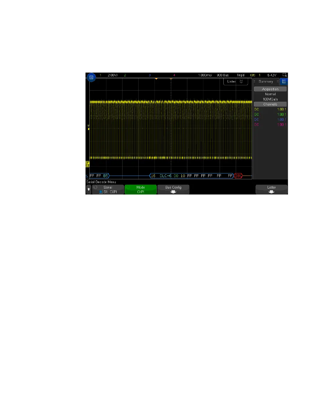
Interpreting CXPI Decode
The CXPI decode display is color coded as follows:
• Blue angled waveforms show an active bus (inside a packet/frame).
• Blue mid-level lines show an idle bus.
• For PTYPE frames, the text "PTYPE" is shown in the decode before the Frame
ID. If the parity bit in the PTYPE field is in error, the "PTYPE" text is displayed in
red.
• Packet/Frame ID — yellow hex digits. The packet/frame ID can optionally show
or omit the leading parity bit.
• Data Length Code (DLC) — cyan. The DLC is always a decimal value.
• Network Management (NM) — green. Binary value, two bits.
• Counter (CT) — yellow. Binary value, two bits.
• Data bytes — white text formatted as a pair of hexadecimal nibbles for each
byte. These hexadecimal bytes are shown with MSB at the left..
• CRC — cyan hex digits when valid, red when error detected.
• Red angled waveforms — Unknown or error condition.
• Flagged error frames — red, with: