CAN/LIN Triggering and Serial Decode 25
Keysight InfiniiVision 3000T X-Series Oscilloscopes User's Guide 403
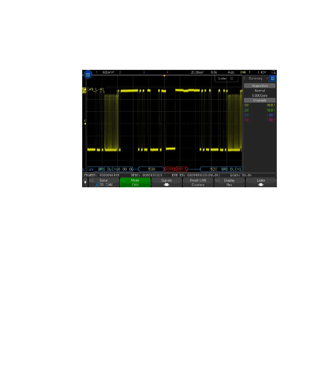
Interpreting CAN/CAN FD Decode
The CAN decode display is color coded as follows:
• Blue angled waveforms show an active bus (inside a packet/frame).
• Blue mid-level lines show an idle bus.
•Frame ID — yellow.
• Data bytes — white hex digits.
• CAN frame type and Data Length Code (DLC) — blue for data frames, green for
remote frames. The DLC is always a decimal value. CAN frame types can be:
• FD — a CAN FD frame whose bit rate does not switch during the data phase.
• BRS — a CAN FD frame whose bit rate switches during the data phase.
• RMT — a standard CAN remote frame.
• Data — a standard CAN data frame.
The status of the Error State Indicator (ESI) flag is shown in the "Type" column
of the Lister. If the ESI bit is recessive, indicating error passive, the background
of the "Type" column will be yellow. If the ESI bit indicates error active, the
"Type" column's background will be unshaded.