CAN/LIN Triggering and Serial Decode 25
Keysight InfiniiVision 3000T X-Series Oscilloscopes User's Guide 407
• All Errors — Finds any form error or active error.
• Overload Frame — Finds CAN overload frames.
When CAN symbolic data is loaded into the oscilloscope (see “Loading and
Displaying CAN Symbolic Data" on page 398), you can search for:
• Message — a symbolic message.
• Message and Signal — a symbolic message and a signal value.
For more information on searching data, see “Searching Lister Data" on page 152.
For more information on using the [Navigate] key and controls, see “Navigating the
Time Base" on page 75.
Setup for LIN Signals
LIN (Local Interconnect Network) signal setup consists of connecting the
oscilloscope to a serial LIN signal, specifying the signal source, threshold voltage
level, baud rate, sample point, and other LIN signal parameters.
To set up the oscilloscope to capture LIN signals:
1 Press [Serial].
2 Press the Serial softkey, turn the Entry knob to select the desired slot (Serial 1 or
Serial 2), and press the softkey again to enable decode.
3 Press the Mode softkey; then, select LIN trigger type.
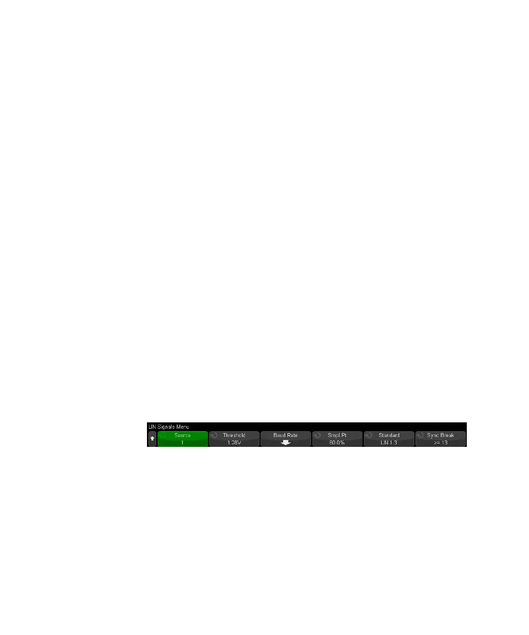
4 Press the Signals softkey to open the LIN Signals Menu.
5 Press the Source softkey to select the channel connected to the LIN signal line.
The label for the LIN source channel is automatically set.
6 Press the Threshold softkey; then, turn the Entry knob to set the LIN signal
threshold voltage level to the middle of the LIN signal.
The threshold voltage level is used in decoding, and it will become the trigger
level when the trigger type is set to the selected serial decode slot.
7 Press the Baud Rate softkey to open the LIN Baud Rate Menu.