Service Guide N5227-90001 5-3
PNA Series Microwave Network Analyzers Theory of Operation
N5227A Network Analyzer System Operation
Network Analyzer System Operation
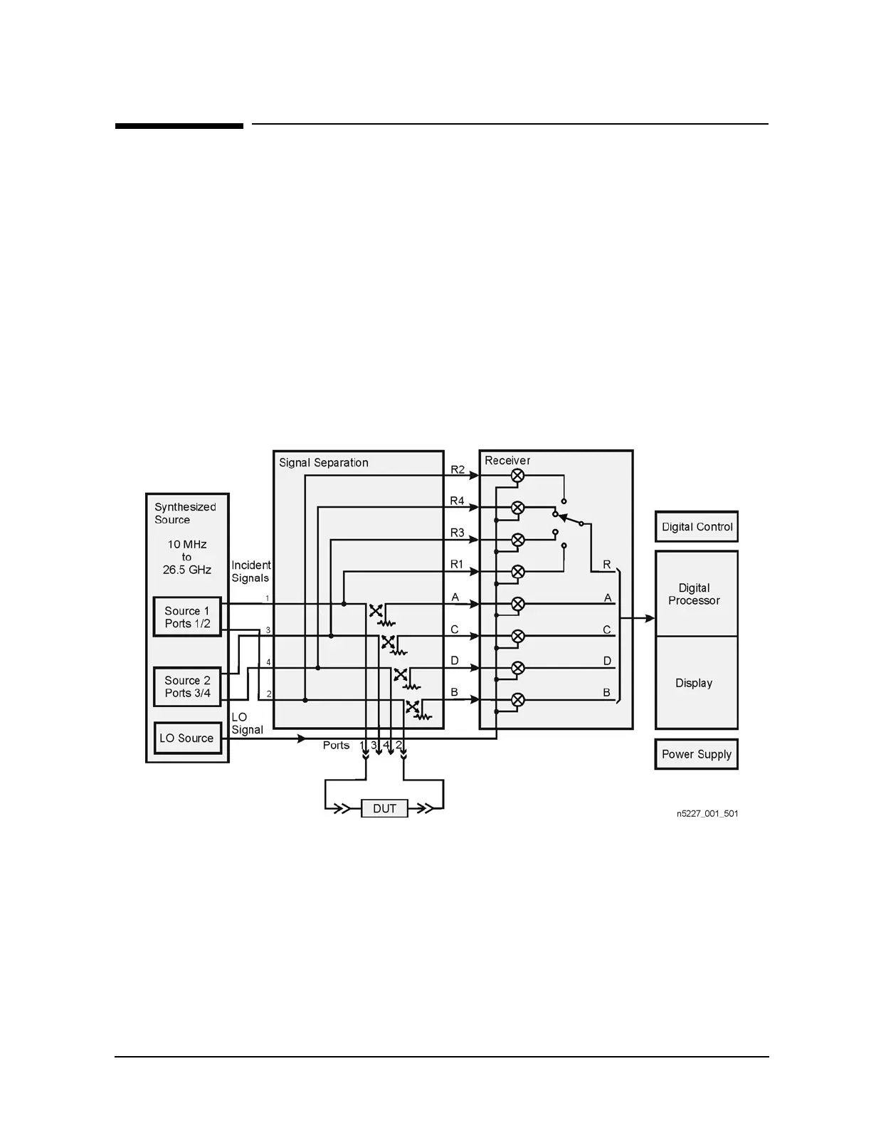
The PNA network analyzer generates two (2-port models) or four (4-port models) phase-locked incident
signals and an LO signal from the internal synthesized source. By means of signal separation, the incident
signals are divided into reference signals and test signals.
The reference signals are applied to the receiver group, while the test signals are applied to the device under
test (DUT) and then to the receiver group. The LO signal is applied directly to the receiver group where it is
mixed with the test and reference signals to produce IF signals for each of the eight receivers (A
–D, R1–R4)
for 4-port models or four receivers (A, B, R1, R2) for 2-port models. These IF signals are downconverted and
then sampled and digitally processed.
Figure 5-1 is a simplified block diagram of the 4-port network analyzer system and Figure 5-2 is a simplified
block diagram of the 2-port network analyzer system.
Figure 5-1 4-Port System Simplified Block Diagram