128
Measuring Digital Communications Signals
Making Burst Power Measurements
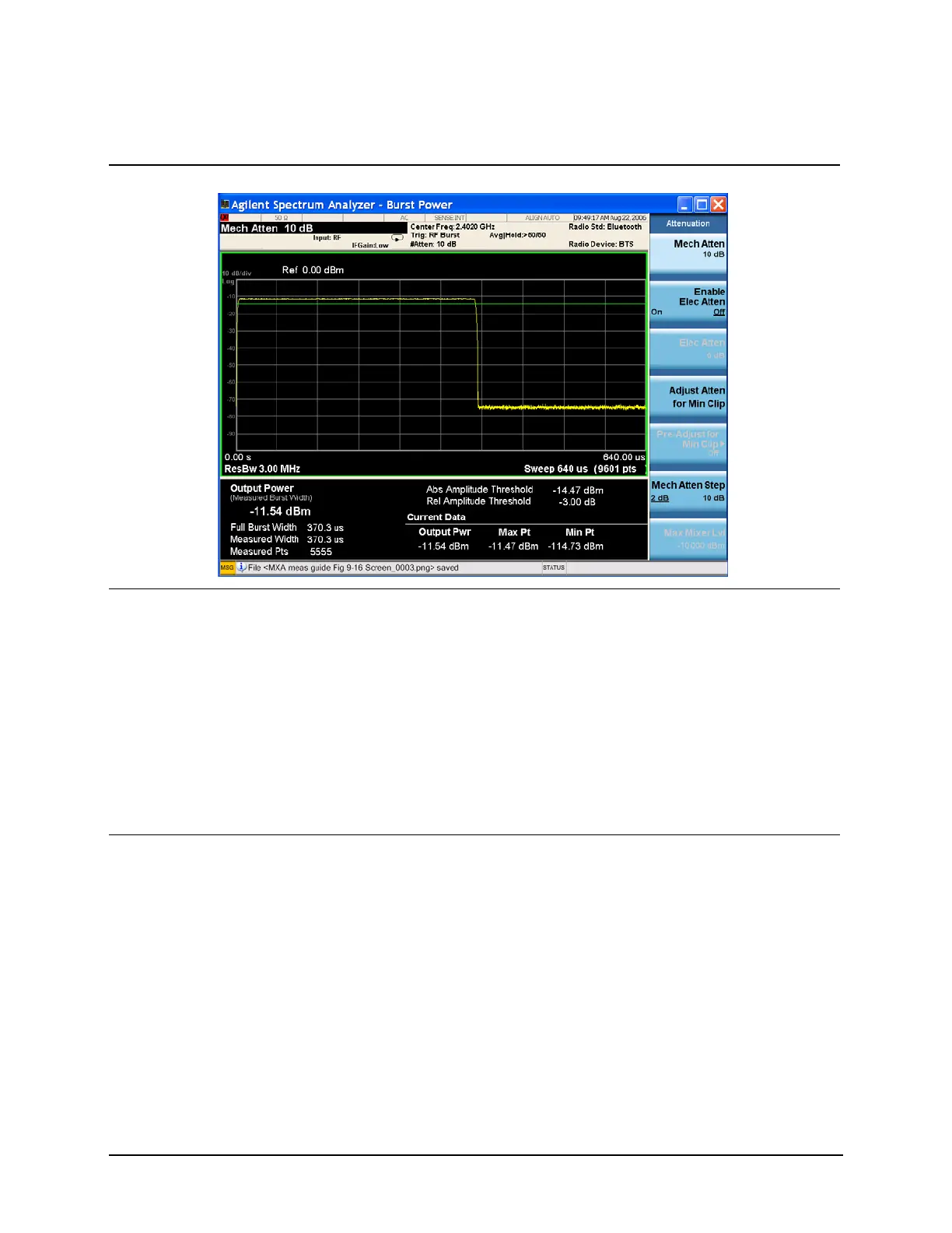
Figure 9-11 Normal Screen Display of Burst Power Measurement Results
9 Select one of the
following three trigger
methods to capture the
bursted signal:
• Periodic Timer Triggering
•Video
•RF Burst Wideband
Triggering (RF burst is
recommended, if
available.
• Press Trigger, RF Burst. For more information on trigger
selections see “Trigger Concepts” on
page 194.
Although the trigger level allows the
analyzer to detect the presence of a
burst, the time samples contributing to
the burst power measurement are
determined by the threshold level, as
described next.
10Set the relative threshold
level above which the
burst power measurement
is calculated.
• Press Meas Setup,
Threshold Lvl (Rel), −10,
dB.
The burst power measurement includes
all points above the threshold and no
points below. The threshold level is
indicated on the display by the green
horizontal line. In this example, the
threshold level has been set to be 10 dB
below the relative level of the burst. The
mean power of the burst is measured
from all data above the threshold level.
Refer to Figure 9-12.
Step Action Notes

 Loading...


