211
Concepts
Time Gating Concepts
Most control settings are determined by two key parameters of the signal under test:
the pulse repetition interval (PRI) and the pulse width (τ). If you know these
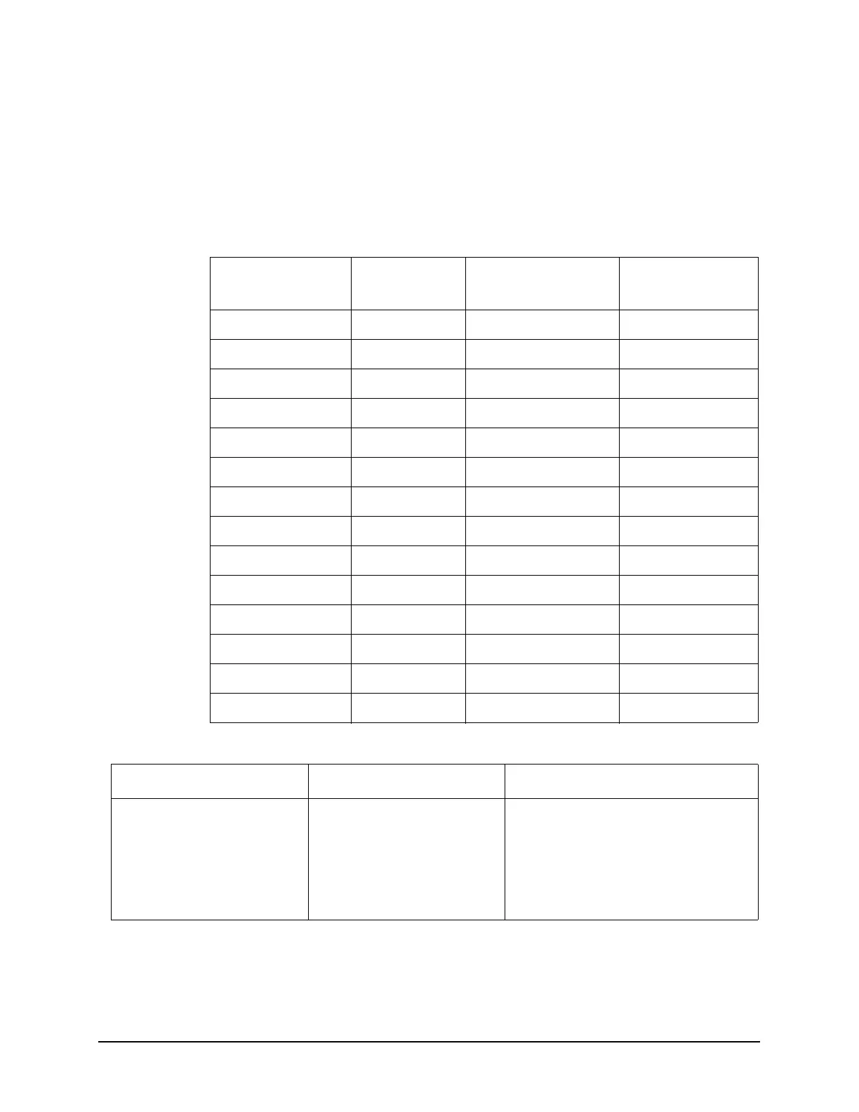
parameters, you can begin by picking some standard settings. Table 15-2
summarizes the parameters for a signal whose trigger event occurs at the same time
as the beginning of the pulse (in other words, SD is 0). If your signal has a non-zero
delay, just add it to the recommended gate delay.
Table 15-2 Suggested Initial Settings for Known Pulse Width (
τ
) and Zero Signal Delay
Pulse wid th (τ) Gate Delay
(SD + τ/5)
Resolution Band width
(>19.5/τ)
Gate Length
(0.7 x τ/4)
4 μs0.8 μs 4.875 MHz 0.7 μs
10 μs2 μs 1.95 MHz 1.753 μs
50 μs10 μs390 kHz 8.75 μs
63.5 μs12.7 μs 307 kHz 11.11 μs
100 μs20 μs 195 kHz 17.5 μs
500 μs100 μs 39 kHz 87.5 μs
1 ms 200 μs 19.5 kHz 0.175 μs
5 ms 1 ms 3.9 kHz 0.875 ms
10 ms 2 ms 1.95 kHz 1.75 ms
16.6 ms 3.32 ms 1.175 kHz 2.905 ms
33 ms 6.6 ms 591 Hz 5.775 ms
50 ms 10 ms 390 Hz 8.75 ms
100 ms 20 ms 195 Hz 17.5 ms
≥130 ms 26 ms 151 Hz 22.75 ms
Table 15-3 If You Have a Problem with the Time-Gated Measurement
Symptom Possible Causes Suggested Solution
Erratic analyzer trace with
dropouts that are not removed
by increasing analyzer sweep
time; oscilloscope view of gate
output signal jumps erratically
in time domain.
Gate Delay may be greater
than trigger repetition interval.
Reduce Gate Delay until it is less than
trigger interval.
Check Gate View to make sure the gate
delay is timed properly.

 Loading...


