5
Assemble units as described herein only. To do otherwise
may result in instability. All screws, nuts and bolts must be
tightened securely and must be checked periodically after
assembly. Failure to assemble properly, or to secure parts
may result in assembly failure and personal injury.
Concerto
®
Seating with Power & Data
Assembly Instructions
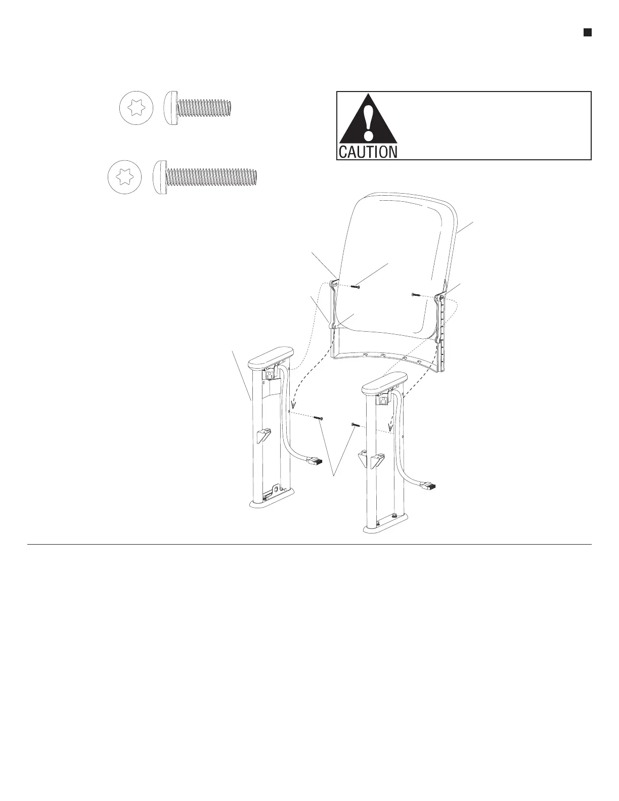
Back Attachment
1. Follow the Concerto
space-planning layout and stage the
backs at their installation location by
specified size (19", 20", 21", 22", 23"
or 24"). Back spacers are riveted to
the sides of the mounting brackets
on 20", 22" and 24" backs.
Note: For the following procedure,
19", 21" and 23" backs will require
use of the shorter
1
/
4
-20 x
3
/
4
" T-30
Torx screws (no spacers). The 20",
22" and 24" backs will require the
longer
1
/
4
-20 x 1
1
/
4
" T-30 Torx
screws.
2. Install either the
1
/
4
-20 x
3
/
4
" or
the
1
/
4
-20 x 1
1
/
4
" T-30 Torx screw
into the lower back mounting hole
on both uprights. For 19", 21" and
23" units, leave a minimum of
3
/
8
"
of threads exposed when using the
3
/
4
" screws; and for 20", 22" and
24" units (with spacers), leave a
minimum of
7
/
8
" of threads exposed
when using the 1
1
/
4
" screws
(Figure 2).
3. Hold the back at a 30° angle behind
the uprights. Hook the mounting
tabs on each side of the back onto
the lower
1
/
4
-20 Torx screws which
were installed in the previous step.
Rotate the backrest forward to line
up with one of the three top holes
specified to achieve the appropriate
back angle. Each hole marks a
4° increment. Unless otherwise
specified, use the center hole. On
20", 22" and 24" units, the spacers
may be repositioned on the mounting
brackets to achieve a different
angle. Remove the spacer rivet and
reposition the spacer to line up with
one of the other two upper mounting
holes on the mounting bracket. Use
the
1
/
4
-20 x 1
1
/
4
" T-30 Torx screw
to help keep the spacer aligned with
the bracket. The backrest will fit
snugly between the uprights and may
need additional inward pressure on
the mounting brackets to squeeze
between the uprights (Figure 2).
Note: The rivets are used to keep
the holes aligned at assembly, and
the back panel properly connected to
the back board. Do not separate the
back panel from the back board when
removing the rivets. Maintain hole
alignment for assembly.
4. Install and tighten the appropriate
1
/
4
-20 Torx screws in the top of both
sides of the unit. Tighten the screws
in the lower holes (Figure 2).
5. Do not tighten any fasteners to the
floor at this time.
lower
/ -20 Torx screws
1
4
upright
mounting tab
back spacer
& 24” seat backs)
back
mounting bracket
back spacer
(for 20”, 22” & 24”
back
1
/ -20 Torx screw
4
Figure 2
13
/ -20 x /”Pan Head T-30 Torx Screw
44
11
/ -20 x 1 /”Pan Head T-30 Torx Screw
44
 Loading...


