2
Assemble units as described herein only. To do otherwise
may result in instability. All screws, nuts and bolts must be
tightened securely and must be checked periodically after
assembly. Failure to assemble properly, or to secure parts
may result in assembly failure and personal injury.
WorkUp Adjustable Table - Model HF
Assembly Instructions
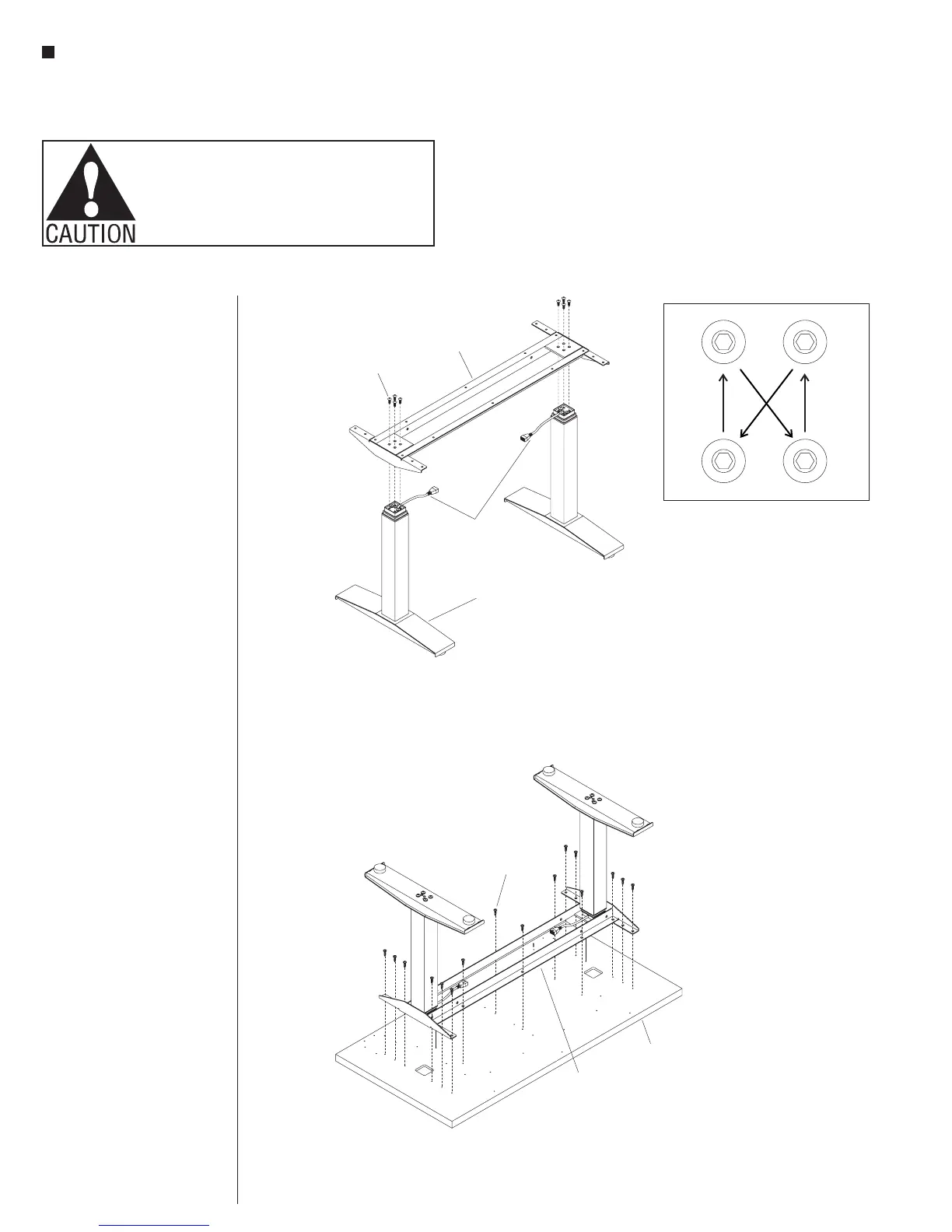
Columns to Worksurface
Support Assembly
1. With the assistance of a
second person, hold both foot/
column assemblies in the
upright position, orienting the
two column cables inward as
illustrated (Figure 2).
2. Position the worksurface support
onto the foot/column assemblies
and allign the four holes in one
end of the support with the four
holes in the column (Figure 2).
3. Attach the worksurface support to
the column using four
M8 x 18mm screws until
snug, then tighten each screw
one quarter turn at a time in a
diagonal pattern until all four
screws are tight (Figure 2 &
Detail A).
4. Attach the second foot/column in
the same manner (Figure 2).
Worksurface Assembly
Note: Except for the “P” shaped
cable clamps, the worksurface is
pre-drilled for installation of all
components.
1. To avoid scratching the table top,
place it with the top side down on
a soft protective material
(Figure 3).
2. Place the worksurface support
with columns on the drilled face
of the table top so the heads
of the M8 bolts set into the
pockets milled in the table top.
The worksurface support should
now be flush with the table top
(Figure 3).
3. Move the worksurface support
with columns slightly to align
the holes in the table top with
those in the worksurface support
(Figure 3).
4. Attach the table top using
#12 x 1” tapping screws in each
available hole (Figure 3).
table top
#12 x 1”
screw
worksurface
support
assembly
worksurface
support
column
cables
foot/column
assembly
M8 x 18mm
screw
Detail A