Assemble units as described herein only. To do otherwise
may result in instability. All screws, nuts and bolts must be
tightened securely and must be checked periodically after
assembly. Failure to assemble properly, or to secure parts
may result in assembly failure and personal injury.
3
WorkUp Adjustable Table - Model HF
Assembly Instructions
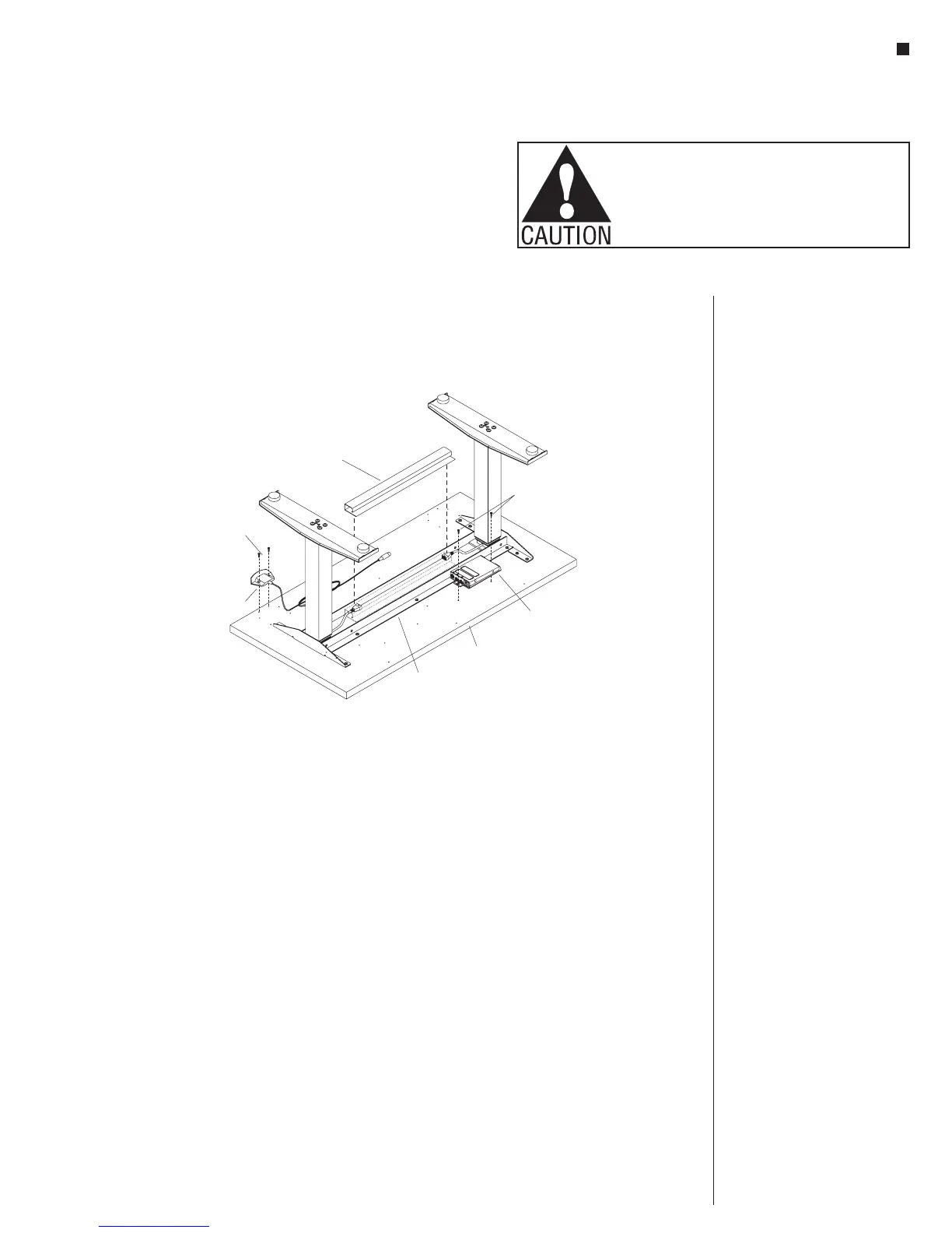
Electric Controls Installation
Note: The keypad may be
mounted to the underside of table
top, at pre-drilled locations on the
right- or left-hand side.
1. Attach the keypad at the left- or
right-hand front edge of the table
using (two screws for standard
keypad) or (four screws for
memory display keypad)
#10 x
11
/
16
”
tapping screws
(Figure 4).
Note: The hole pattern for the
keypad will accommodate the
standard keypad and the memory
display keypad, so all holes will
not be used.
2. Position and mount the control
box to the underside of the table
tops at one of two pre-drilled
hole locations. Attach the control
box at the left- or right-hand
side of the table top behind the
worksurface support using two
#12 x 1” screws (Figure 4).
3. If the optional plastic wire trough
was ordered, expose the two sided
tape and install it between the two
steel angles of the worksurface
support (Figure 4).
#12 x 1”
screws
table top
control
box
worksurface
support
keypad
#10 x /”
11
16
screw
plastic wire
trough
(optional)
4