Assemble units as described herein only. To do otherwise
may result in instability. All screws, nuts and bolts must be
tightened securely and must be checked periodically after
assembly. Failure to assemble properly, or to secure parts
may result in assembly failure and personal injury.
4
WorkUp Adjustable Table - Model HF
Assembly Instructions
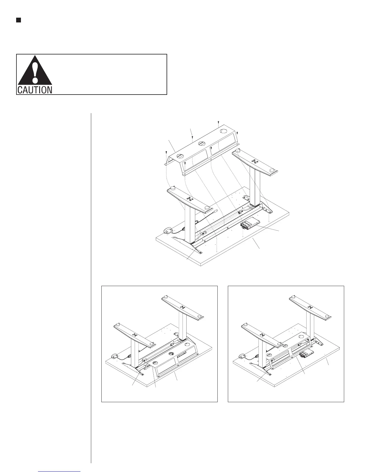
Wire Trough
Note: The wire trough is an
optional part that must be ordered
separately. If no wire trough is
specified, go now to page 5.
1. An optional wire trough may
mount to the underside of the
table top, centered over the
worksurface supports of any
depth table, as illustrated in
Detail C. If the wire trough is
not center-mounted over the
worksurface supports, the
table top depth determines the
mounting location. If the wire
trough is to be mounted under
table tops of 22” or 24” in depth,
see Figure 5. If the wire trough is
to be mounted under tops of 30”
or 36” in depth, see Detail B.
2. Align the wire trough mounting
holes to the appropriate holes in
the table top. Using six #10 x
5
/
8
”
pan head screws, secure the
wire trough to the table top as
illustrated (Figure 5, Details B
or C).
table top
box
worksurface
support
or 24”Table Top Depth
wire trough
(optional)
8
pan head
screw
Detail B - 30” or 36”Table Top Depth
worksurface
support
table
top
wire
trough
Detail C - 22”, 24”, 30” or 36”Table Top Depth
worksurface
support
table
top
wire
trough