13
Assemble units as described herein only. To do otherwise
may result in instability. All screws, nuts and bolts must be
tightened securely and must be checked periodically after
assembly. Failure to assemble properly, or to secure parts
may result in assembly failure and personal injury.
Seminar
TM
Tables with 4-Wire Power System - Jumper Covers
Assembly Instructions
Seminar Tables with 4-Wire
Power System (cont.)
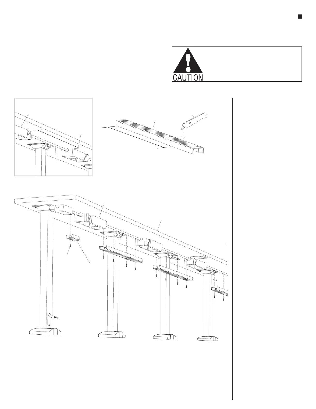
Note: 4-Wire Power System jumper
covers must be properly cut to size at
the installation location. Take care when
measuring and cutting.
25. Begin installation of jumper covers
at one end of the unit and carefully
measure the distance between two
receptacle hub shrouds, or between
an installed power infeed shroud
and the next receptacle hub shroud
at the location to receive a jumper
cover under the tabletop. The
measurement should be made so
the cut jumper cover will fit between
the shrouds, cover the knock-out
ends of the shrouds as well as the
receptacle jumpers (Detail G).
26. Place a jumper cover onto a
protective surface and transfer the
measurement from step 25 to the
cover. Using a utility knife, cut the
jumper cover along the slits in the
cover, then cut down along the
sides and separate the cover apart
(Figure 12).
27. Position the correctly sized cover
up between the receptacle hub and/
or power infeed shrouds, centered
over the receptacle jumper. At
mounting hole locations along
the length of the jumper cover,
insert #10 x
3
/
4
” screws and secure
the cover to the underside of the
tabletop. Do not over-tighten,
torque the screws to 25 in/lb
(Figure 13).
28. Follow steps 25 through 27 above
to cut, fit and install the remaining
jumper covers.
13
Figure 12
jumper cover
measure
(distance between shrouds)
utility
knife
receptacle hub
shroud
receptacle hub
shroud
measure
receptacle
jumper
#x /”10
3
4
screw
jumper cover
(cut to length)
Detail G
tabletop
receptacle hub
shroud