17
Assemble units as described herein only. To do otherwise
may result in instability. All screws, nuts and bolts must be
tightened securely and must be checked periodically after
assembly. Failure to assemble properly, or to secure parts
may result in assembly failure and personal injury.
Seminar
TM
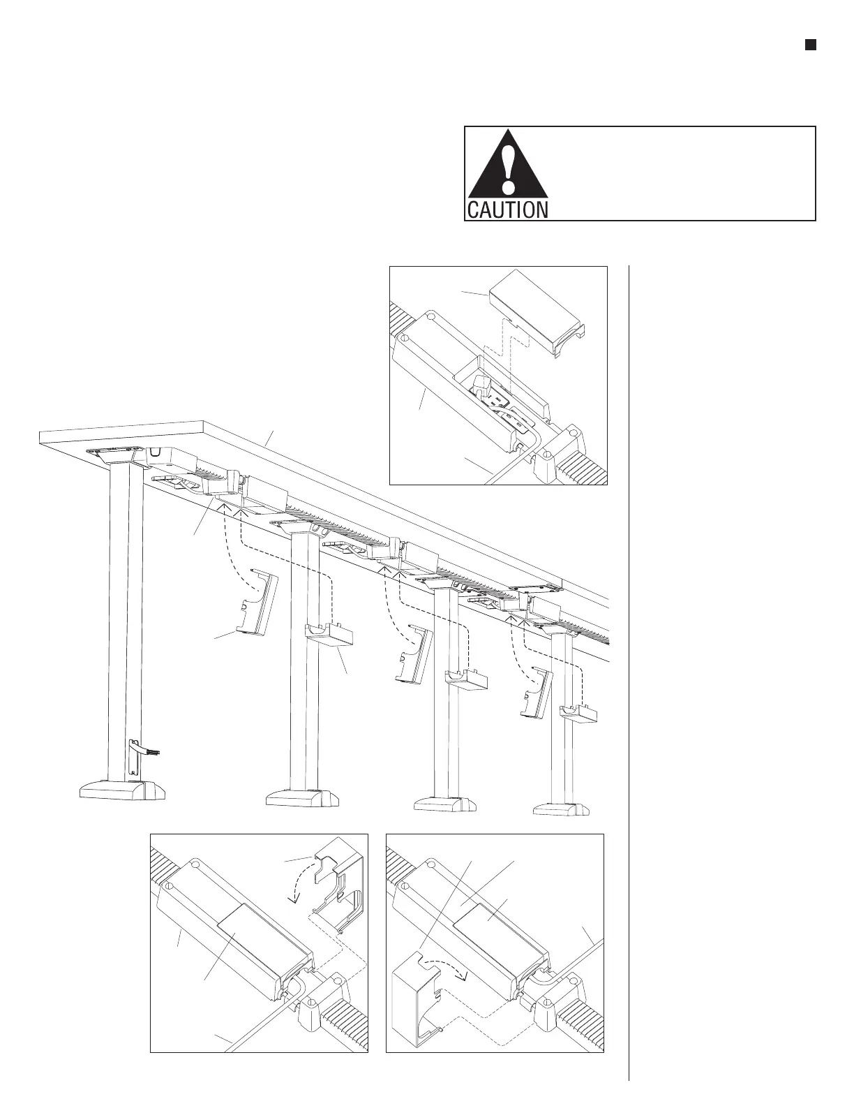
Tables with 4-Wire Power System - Excess Cord Covers
Assembly Instructions
tabletop
power module
cord & plug
power module
cord & plug
power module
cord & plug
excess cord
dump shroud
excess
cord
dump
shroud
excess cord
dump shroud
cord plug
cover
cord plug
cover
cord plug
cover
cord plug
cover
receptacle
hub shroud
receptacle
hub shroud
receptacle
hub shroud
receptacle
hub shroud
Detail K
Detail L Detail M
Figure 17
Cord Plug Covers Installation
35. Once all power modules are
plugged into the duplex receptacles
in the installed receptacle hub
shrouds, the cord plug cover can
be installed to the hub shrouds.
Position the cord plug cover as
illustrated and insert the teeth of
the cord cover into the slots of the
receptacle hub shroud, then slide
the cord cover towards the closest
end of the hub shroud to lock in
place (Figure 17 & Detail K).
Note: The power module type
and exit location of the power cord
from the receptacle hub shroud will
determine which orientation the
excess cord dump should will be
installed (Details L & M).
36. Next, prepare to install the excess
cord dump shroud to the receptacle
hub shroud by first determining
which side the power module’s
cord exits the receptacle hub
shroud (Details L & M). Orient
the cord dump shroud correctly
and slide the tabs at both sides of
the shroud end into the key slots
of the receptacle hub shroud as
illustrated. Once slid in, the cord
dump shroud is hinged in place.
Gather excess cord into the dump
cover, swing it up and snap it into
place on the receptacle hub shroud
(Figure 17, Details L & M).