18
Assemble units as described herein only. To do otherwise
may result in instability. All screws, nuts and bolts must be
tightened securely and must be checked periodically after
assembly. Failure to assemble properly, or to secure parts
may result in assembly failure and personal injury.
Seminar
TM
Tables with 4-Wire Power System - Power Infeed
Assembly Instructions
Power Infeed Wiring
Note: All table connections (joint
fasteners and splice plates) must be
securely fastened before electrical
components can be installed.
Note: The power infeeds may now
be connected to the power source
by a qualified electrician who must
also check the electrical integrity
of the finished system. Step 29 is
intended as a guideline for this part
of the installation.
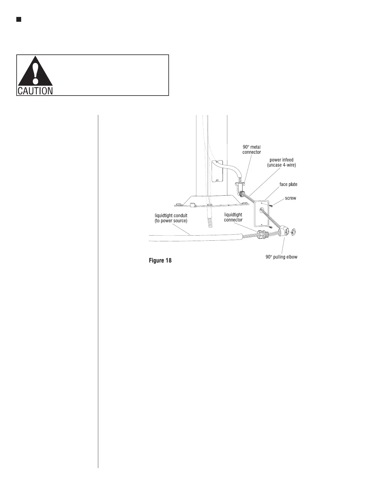
37. Note the one open
7
/
8
” knockout on
the face plate. Route the uncased
4-wire ends through the 90° metal
connector, face plate knock-out
hole, 90° pulling elbow and
liquid-tight connector. Fasten
components together. Cut uncased
4-wire and liquid-tight conduit
to desired lengths. Feed uncased
4-wire through liquid-tight conduit
and attach to 90° connector on the
front of the face plate. Attach face
plate to vertical leg member with
screws provided. Attach uncased
4-wire to power source (Figure 18).