21
Assemble units as described herein only. To do otherwise
may result in instability. All screws, nuts and bolts must be
tightened securely and must be checked periodically after
assembly. Failure to assemble properly, or to secure parts
may result in assembly failure and personal injury.
Seminar
TM
Tables with 4-Wire Power System - Modesty Panels
Assembly Instructions
tabletop
steel
modesty panel
#10 x /”
1
2
screws
(12.0110.XX)
#14 x 1”
screws
(12.0275)
#10-24 keps nut
(12.0023.TM)
modesty panel
bracket
modesty panel
see detail on
space plan
bottom of table
view of corner
1
/”
4
drill /”hole
1
4
through dimple
dimpled panel only
modesty panel
with return
1
/”
4
end of tabletop
splice plate
#10-24 keps nut
(12.0023.TM)
#10 x /”
1
2
screws
(12.0110.XX)
bottom of table
splice plate
Detail O Detail P
Detail Q Detail R
see
detail on
space
plan
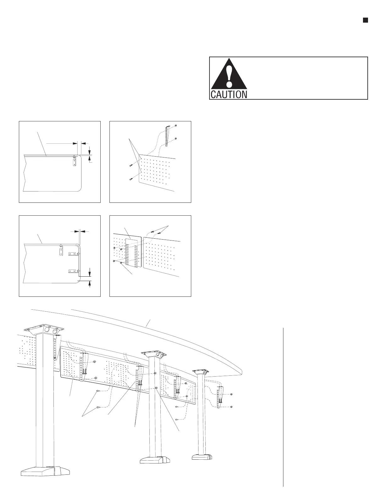
Figure 21
tabletop
steel
modesty panel
#10 x /”
1
2
screws
(12.0110.XX)
#14 x 1”
screws
(12.0275)
#10-24 keps nut
(12.0023.TM)
modesty panel
bracket
modesty panel
see detail on
space plan
bottom of table
view of corner
1
/”
4
drill /”hole
1
4
through dimple
dimpled panel only
modesty panel
with return
1
/”
4
end of tabletop
splice plate
#10-24 keps nut
(12.0023.TM)
#10 x /”
1
2
screws
(12.0110.XX)
bottom of table
splice plate
Detail O Detail P
Detail Q Detail R
see
detail on
space
plan
Steel Modesty Panel Installation
41. Per the space-planning layout and
the identification numbers on the
back side of each modesty panel,
lay the steel modesty panels out
where they will be installed to the
tabletops. Modesty panel lengths
are undersized on each end thereby
creating a
1
/
2
” gap at the modesty
panel joints, and a
3
/
4
” to 2
1
/
2
”
space at the end-of-run.
Note: Care must be taken when
positioning the brackets to
ensure they do not interfere with
the tabletop support flange. On
the modesty panel ends, use an
appropriate left- or right-hand
bracket so that the nuts are not
visible.
42. Refer to the chart on the installation
drawing for the number of modesty
panel brackets required per
modesty panel, and equally space
the brackets along the panel. A
modesty panel bracket must
be installed to the end set
of holes on both sides of the
modesty panel. Begin assembly
by installing the bracket to the
modesty panel first. The longer
flange of the bracket should be
secured to the modesty panel with
two #10 x
1
/
2
” screws and #10-24
keps nuts. Tighten nuts to 35 in/lb.
Insert the screws through the top
hole in the panel and into the 3rd
hole from the top on the bracket.
The lower screw should be routed
through the modesty panel so that
it secures to the aligned hole in the
bracket. A modesty panel bracket
must be installed to the end set of
holes on both sides of modesty
panel (Figure 21).
Note: For dimpled panels,
drill
1
/
4
” holes through the top and
5th dimples in panel at bracket
locations using the dimple as a
guide (Detail P).
43. After all brackets are secured,
carefully lift the panel up and install
the brackets to the underside of
the tabletop using #14 x 1” screws
torqued to 100 in/lb. Mounting
holes must be pre-drilled with a
3
/
16
” drill bit to a maximum depth
of
3
/
4
”. The modesty panel must be
mounted
1
/
4
” from the front edge of
the tabletop and in from the end of
the tabletop per the space-planning
layout (Detail O).
44. Panels with a return at the end will
require two brackets mounted at
the end of the panel as illustrated
(Detail Q).
45. For continuous metal modesty
panels only, attach the 16-gauge
metal splice plate between the ends
of the modesty panels to ensure
proper alignment from panel to
panel. Install in the same manner
as brackets using #10 x
1
/
2
” screws
with #10-24 keps nuts (Detail R).
Tighten nuts to 35 in/lb.
 Loading...


