Do you have a question about the Kicker ZR1000 and is the answer not in the manual?
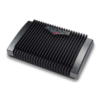
New heatsink for heat dissipation, with thermal, overvoltage, reverse polarity, and short circuit protection.
Gold-plated connectors, upgraded power supply switching MOSFETs for better thermal stability and sound.
Extensive use of surface mount devices throughout the design to increase reliability.
Includes ZRX Crossover Module, active signal processing, RCA outputs, optical isolation, DC servo circuit, silent turn-on/off.
Multiple amplifiers can be daisy chained without signal degradation due to 22,000 Ohms input impedance.
Recommends installation by an authorized dealer for longer warranty.
Amplifier orientation is critical for cooling; fins should be vertical or flat with fins up.
Keep chassis isolated from vehicle metal to prevent ground loops; use plastic inserts.
Plastic inserts accept #8 screws for mounting.
Speaker connectors accept up to 8 gauge wire; ZR360/600/1000 power/ground use 4 gauge.
Connect ground wire (<= 24 inches) to bare metal chassis, not directly to battery.
Run positive wire directly to battery positive terminal with an inline fuse within 18 inches.
Chart for minimal loss at full rated power based on wire length and model.
Keep signal wires away from power wires; cross at 90 degrees if necessary.
Specifies inline fuse ratings for each model (ZR120 to ZR1000).
Amplifier equipped with ZRX module for low pass, high pass filtering, or bypass mode.
Explains Bypass, Low Pass (80Hz), and High Pass (100Hz) modes for the ZRX module.
Active Signal Processing Module must be installed for operation; do not power up without module or change module when powered.
Diagrams showing typical installations like daisy chaining and adding to factory stereo.
Details crossover slope (12dB/octave) and crossover points (80Hz low pass, 100Hz high pass).
Details minimum impedances for stereo (1 Ohm) and bridged mono (2 Ohm) operation.
Diagram and description for connecting signal and speakers in stereo mode.
Diagram and description for connecting signal and speakers in bridged mono mode.
Connects the input of one amplifier to the output of the first for same frequency range operation.
Gain control is for level matching, not power adjustment; adjusts amplifier sensitivity.
Procedure to set gain by raising source level and then amplifier gain until distortion is audible.
Allows use of KICKER Modules to increase amplifier versatility at low cost.
2-way modules for separate amplifiers (SWX, MRX, TWX) with selectable crossover frequencies.
Various modules like EEM, EQM, CRM, RGX, PBM, KEQ, MMDP for specific functions.
Explains LED behavior and basic checks using a VOM for power and remote turn-on issues.
Covers thermal protection, overcurrent protection, and voltage issues indicated by the yellow LED.
Troubleshooting steps for whistling noise following engine RPM, checking grounds and RCA routing.
Addresses unfocused stereo image and reduced bass by checking system phasing and speaker wiring.
Caution regarding correct jumper cable connections to avoid blown fuses or system damage.
Table detailing rated power for different models in stereo and bridged mono configurations.
Lists common specs like distortion, frequency response, signal-to-noise ratio, input impedance, and sensitivity.
Details 3-year warranty (dealer install) or 1-year (DIY), and replacement policy.
Steps to follow for warranty service, including returning to dealer or contacting customer service for RA number.
Lists exclusions from warranty, such as improper installation, misuse, or unauthorized repairs.
States a goal of 24-hour service for returns, subject to inventory.
Advises contacting international dealers for country-specific warranty policies.
Warning about potential hearing damage from high sound levels and distortion.
| Channels | 1 |
|---|---|
| Signal to Noise Ratio | >95dB |
| Power Output (RMS) | 1000W |
| RMS Power at 4 Ohms | 500W |
| RMS Power at 2 Ohms | 1000W |
| Bass Boost | 0dB - 18dB |
| Fuse Rating | 40A |
| Crossover | Variable Low-Pass |