[5]
Operation mode
indicator
Displays the
specified operation mode in green. The actual
operation status
is indi-
cated in red.
[6]
ABC preset
memory indicator
When
an
ABC preset memory is recalled, the corresponding
LED illuminates.
[7]
Channel display
Displays the channel number of the load
unit. The channel
numbers
are
assigned to
the installed slots from
the left facing the front panel starting
with
CHI.
[8]
Measured value
display
Displays the
measured value of the load
unit
in
combination
with
the unit
indicator.
Displays
voltage/current,
voltage/power, current/power, elapsed time/alarm,
or the
input voltage when
the load turns off. Press the DISP key
to switch the display. An
alarm remains
displayed until it is cleared.
[9]
Unit indicator
Indicates the unit of
the measured
value using an LED.
[10]
SW, SEQ, EXT, and
ALM indicators
[10-1]
SW
Illuminates in switching
mode.
[10-2]
SEQ
Illuminates in
sequence mode.
[10-3]
EXT
Illuminates in external
control mode.
[10-4]
ALM
Illuminates when an
alarm occurs.
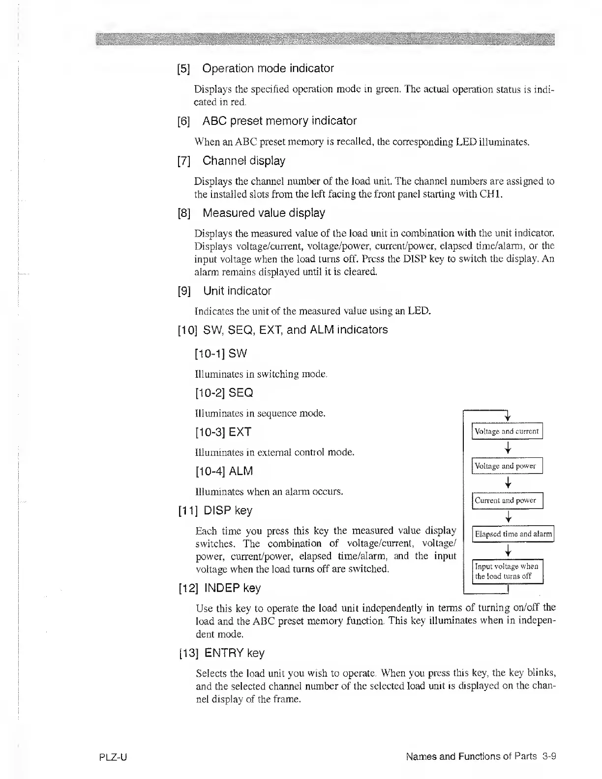
[11]
DISP key
Each time you press
this key the measured
value display
switches.
The
combination of
voltage/current,
voltage/
power, current/power, elapsed
time/alarm, and the input
voltage when the load
turns off are switched.
[12]
INDEPkey
Use this key to
operate the load unit
independently in terms
of turning
on/off the
load and the ABC
preset memory
function. This key
illuminates when in
indepen-
dent mode.
[13]
ENTRY key
Selects the load unit
you wish to operate. When you
press this key, the key
blinks,
and the selected channel
number of the selected load
unit is displayed on the
chan-
nel display of the
frame.
Voltage and current
Voltage and
power
1
Current and
power
Elapsed time and
alarm
1
Input
voltage when
the
load turns off
PLZ-U
Names and Functions
of Parts
3-9

 Loading...