3.1.2 Load Unit
(Channel)
ELECTRONIC
LOAD PLZ^5Qi:K\
I^IKlkUSUil
LOAD
ENTRV INOEP OISP
|H
[14]
Air
iniet
(Louver)
[1]
DC INPUT(-)
[8]
Measured value
display
[7]
Channel display
[6]
ABC preset
memory
_
indicator
[5]
Operation mode
indicator
[4]
Range
indicator
[2]
Front remote sensing
terminal
[1]
DC INPUT(+)
[3]
LOAD
[9]
Unit indicator
[10-1]
SW
[10-2]
SEQ
[10-3]
EXT
[10-4]
ALM
[11]
DISP
[12]
INDEP
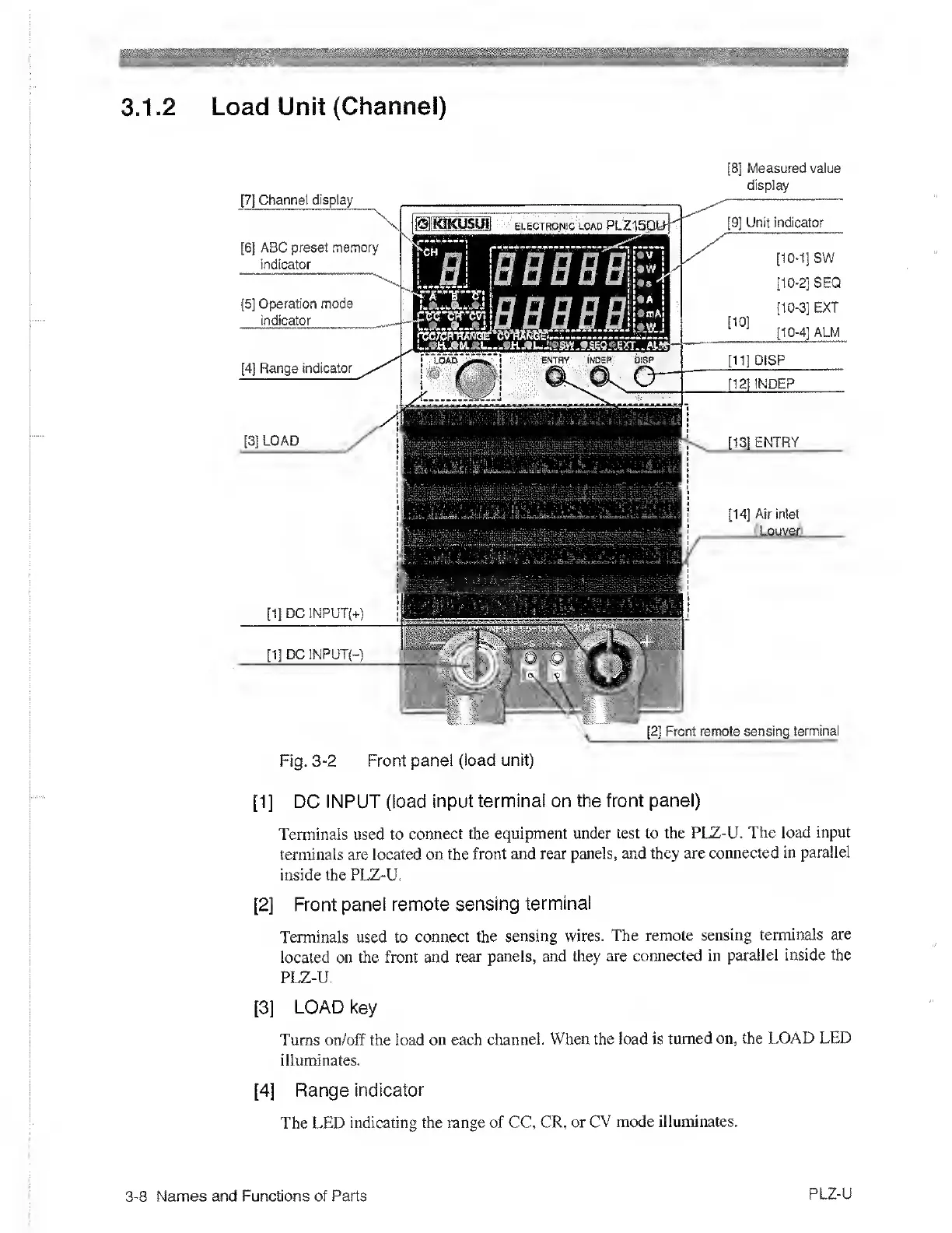
Fig.
3-2
Front panel
(load unit)
[1]
DC INPUT (load
input
terminal on the front panel)
Terminals used to
connect the
equipment under test to the PLZ-U.
The
load input
terminals are located on
the front and
rear panels, and they
are connected
in parallel
inside the
PLZ-U.
[2]
Front
panel remote sensing
terminal
Terminals used to connect
the sensing wires.
The
remote sensing
terminals
are
located on the front and
rear panels, and
they are
connected in
parallel inside the
PLZ-U.
[3]
LOAD key
Turns on/off the load
on each
channel. When the load is
turned on, the
LOAD LED
illuminates.
[4]
Range
indicator
The LED
indicating the range of CC,
CR, or
CV mode illuminates.
3-8
Names and Functions of Parts
PLZ-U

 Loading...