Remote
sensing is a
function used to compensate
for the
voltage
drop caused by the
resistance of the load
wire when it cannot be neglected. Execute remote
sensing to
accurately
set the resistance
and voltage and measure
the voltage and power.
Since
remote sensing improves
the transient characteristics
in CC and CR modes,
operational stability can be
achieved.
•
If the load wire
comes loose while
executing remote sensing, the PLZ-U
may malfunction.
Check that the
connection is secure. You can prevent
accidents
by connecting
a protection fuse
(see Fig. 5-9). Use a fuse with a
rated
current of 0.1 A
and a rate voltage
greater than the output voltage of
the
equipment under
test.
•
Pay attention to
the polarity of remote
sensing. Reversing the
connection
can cause damage
to the PLZ-U.
Insert a protection fuse in
the wiring.
•
If you
are not using
remote sensing,
remove
the
remote
sensing wires
from the
PLZ-U.
Remote
sensing
wiring
INOTEl
•
Use AWG24
wires for the
remote sensing terminals on
the front panel. Use
AWG24
or thicker wires for
the remote sensing terminals
on the rear panel.
•
For the
remote sensing
terminals on the rear panel, use
crimp terminals
for M3
screws.
1L
Turn off the output
of the equipment
under test.
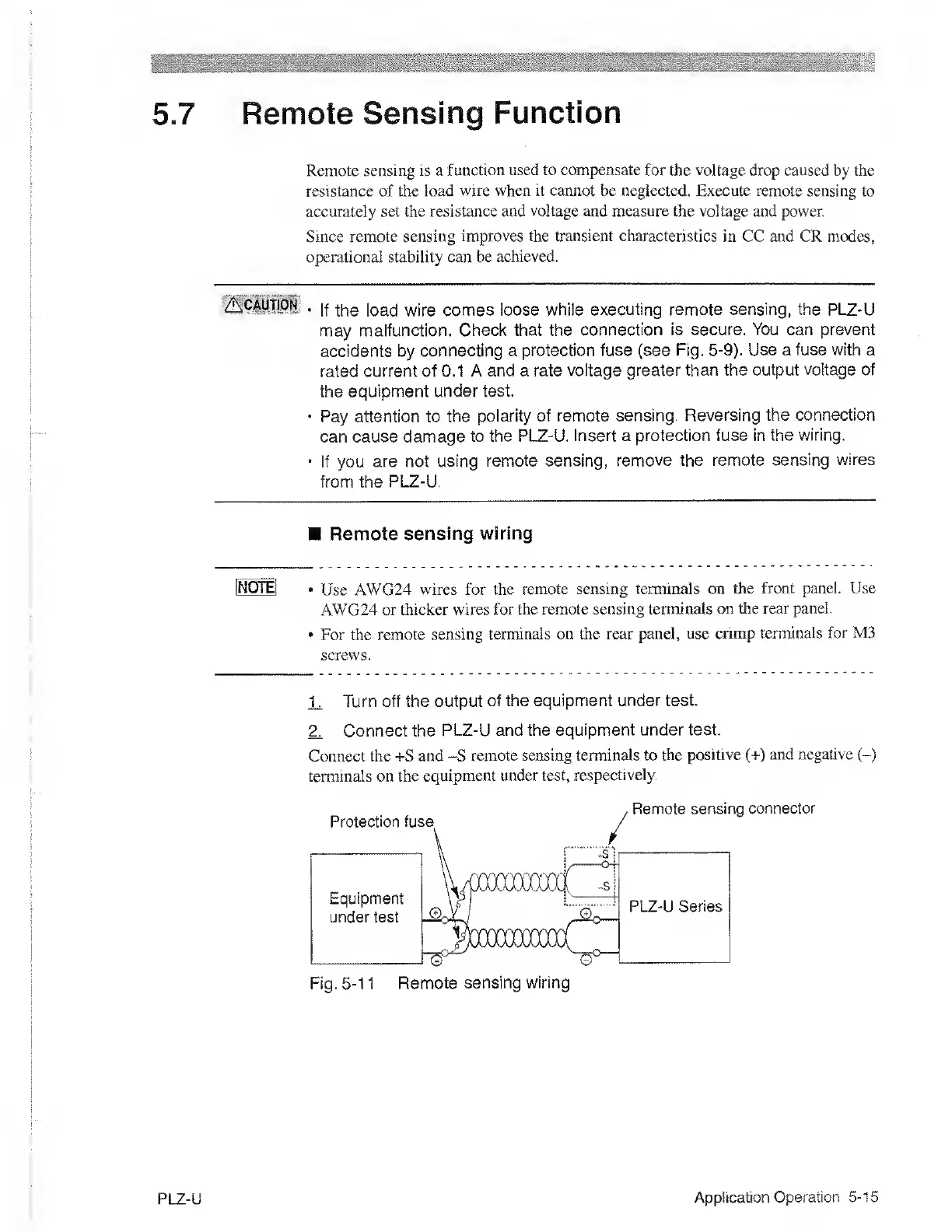
Z Connect the
PLZ-U and the
equipment under test
Connect the -i-S and -S
remote sensing terminals to
the positive
(+)
and negative
(-)
terminals on the
equipment under test,
respectively.
PLZ-U
Application
Operation
5-15

 Loading...