TOS8870A
OPERATION PROCEDURE
13
4) Setting the test time
1. With the timer, set the test time of the DUT as required of standards, and other.
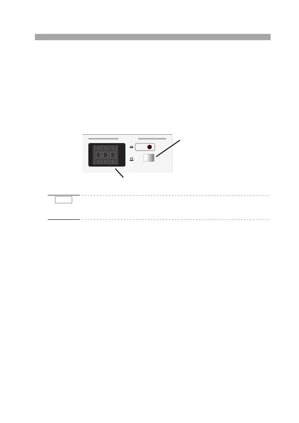
Selecting the timer range
The timer of the tester can be set to 0.2 to 99.9 seconds (in a withstanding voltage test) and 1
to 999 seconds by operating the time setup switch and the range selector switch next to it.
When the range selector switch is protruding, the setting of the time setup switch equals the
timer setting. When the range selector switch is pressed, the timer setting equals the setting of
the time setup switch multiplied by 0.1.
The setting of the timer setup switch can be changed by pressing the switches above and
below the numbers.
Fig.3-1
• In a withstanding voltage test, be sure to set the timer to 0.2 seconds or longer period.
• In an insulation resistance test, be sure to set the timer to 0.5 seconds or longer period. Refer
to " Waiting-time for Judgement in Insulation Resistance Test" on page 19.
5) Setting the test voltage
1. Set both TIMER ON/OFF switch and LOWER ON/OFF switch to the OFF state.
2. Check that the PROTECTION lamp is not illuminating.
If the PROTECTION lamp is illuminating, press the STOP switch once and then perform
the above procedure.
3. Check that the TEST VOLTAGE dial is at fully counterclockwise position
4. Press the START switch.
5. Adjust the test voltage by gradually turning clockwise the TEST VOLTAGE dial and read-
ing the voltage on the voltmeter.
6. Cutoff the output by pressing the STOP switch.
7. Set the TIMER ON/OFF switch to the ON state.
6) Connecting the DUT
1. Make sure that the output voltmeter indication is zero.
2. Make sure that the DANGER lamp is not illuminating.
3. Connect the LOW test leadwire to the LOW terminal of the Tester.
4. Connect the high voltage test leadwire to the HIGH VOLTAGE terminal.
5. Short the high voltage test leadwire to the LOW test leadwire to make sure that no high
voltage is being delivered to the output terminal.
6. Connect the LOW leadwire to the DUT.
7. Connect the high voltage test leadwire to the DUT.
S
TIMER
x0.1
x1
Range selector switch
Time setup switch
9 9 9
+
-
+
-
+
-
NOTE

 Loading...


