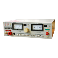
TOS8870A
OPERATING PRINCIPLE
29
4.2 Description of Individual Circuits
[1] High voltage prestabilization circuit
To obtain a high DC voltage required for an insulation resistance test, rough stabilization is carried
out using a step-up converter to obtain about 1 150 V.
[2] High voltage stabilization circuit
Stabilizes the above DC voltage more finely, in order to be applied as an insulation resistance test
voltage to the DUT.
The test voltage is a negative voltage of nominal 1 000 V or 500 V.
[3] Discharge circuit
This circuit forcibly discharges the DUT, which was charged once at the end of an insulation resis-
tance test, for about 70 ms using a resistor of about 150 k
Ω
.
[4] Current detector circuit with log converter
The current which flows in the DUT varies ranging from less than 1 µA to approximately 1.2 mA
when shorted.
To detect and indicate this wide dynamic range current on the single range scale of the ohmmeter,
this circuit has a log converter which converts the detected signal into a logarithmic signal. A
highly accurate log converter is used in order to satisfy the specification accuracy.
[5] Ohmmeter
This meter is driven by the above logarithmic signal to indicate the insulation resistance of the
DUT.
[6] High limit reference value setting circuit
Sets the high limit reference value for PASS-FAIL judgement. The value is adjustable with its
potentiometer on the front panel.
[7] Low limit reference value setting circuit
Sets the low limit reference value for PASS-FAIL judgement. The value is adjustable with its poten-
tiometer on the front panel.
[8] Window comparator
Generates a PASS signal if the measured value is within the range between high and low limit refer-
ence values. If not, generates a FAIL signal.
[9] Relay
On-off controls the power applied to the voltage regulator for withstanding voltage test. A solid-
state zero-start type relay circuit is employed to minimize transiential spike voltages caused when
the high voltage output is turned on or off.
[10] Voltage regulator
A slide transformer is used to control the output voltage.
[11] High voltage transformer
Boosts the voltage regulator output with a ratio of 1:25 or 1:50 into a high output voltage of 0 to
2.5 kV or 0 to 5 kV. The rating is 5 kV, 100 mA (500 VA) when the AC line voltage is 100 V.
[12] Voltmeter
Indicates the output voltage for withstanding voltage test.

 Loading...