26
OPERATION PROCEDURE
TOS8870A
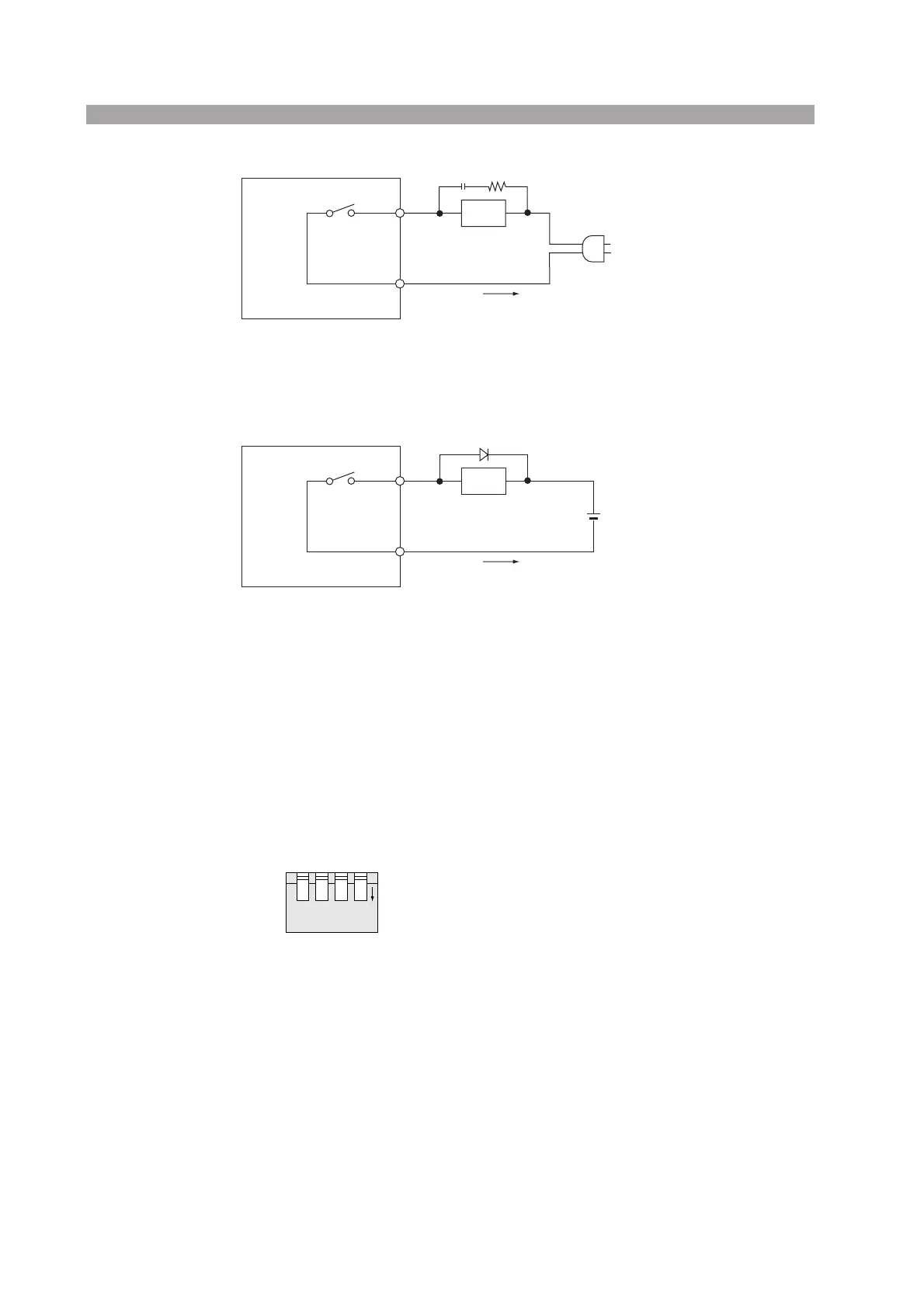
Fig.3-14
Fig.3-15
3.7 Special Test Modes
Four types of special modes are selectable with the TEST MODE selector switches on the rear
panel. The standard positions of the switches (the positions as the switches are set as the Tester is
shipped) are the OFF positions as shown in Fig.3-16.
By throwing the switches to the ON positions, respective modes as described below can be selected.
Since mode settings are mutually independent, any combinations of switch settings are possible.
Fig.3-16 STANDARD POSITIONS
■
DOUBLE ACTION
For the DOUBLE ACTION mode, set the switches as shown in Fig.3-17.
When in the RESET state in the standard mode, as you press the START switch, the Tester is driven
into the TEST ON state.
In this mode, testing cannot be performed simply by pressing the START switch. Testing will only
start when the STOP switch is pressed followed by the START switch within about 0.5 seconds.
While the procedure is more complicated due to the double switch actions, a higher safety of test
can be attained.
The function is the same as above also when in the remote control mode.
TOS8870A
100 VAC
Less than 1 A
LOAD
C
R
R : Approx. 100 Ω, 2 W or over
C : Approx. 0.1 µF, 250 VAC or higher
(The R and C are reference values only. Select proper values
in accordance with the actual conditions.)
TOS8870A
Less than 1 A
Diode
Reverse voltage : 200 V or higher
Foward current : 1 A or more
(Tha diode ratings are reference value only. Select proper values
in accodance with the actual conditions.)
Less than
30 V
LOAD
1234
ON


 To Next Page