TOS8870A
SPECIFICATIONS
37
Chapter 7 SPECIFICATIONS
This Chapter provides electric and mechanical specifications and descriptions of options.
7.1 Withstanding Voltage Tester
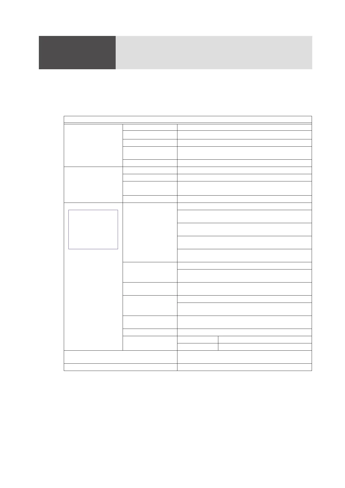
Table 7-1
WITHSTANDING VOLTAGE TESTER
Test Voltage Applied AC Voltage 0 V to 2.5 kV/0 V to 5 kV (tow ranges)
Output Rating
500 VA (5 kV, 100 mA with 100 V line voltage).
*1
*1. The heat radiation of the output section of the tester is designed to be 1/2 of the rated output, taking the size, weight,
cost, etc., into consideration. Therefore, use it within the limitations shown in Table7-2. If it is used in excess of
these limitations, the temperature of the output section rises excessively and the internal protection circuit may be
activated. In this case, cancel the test for a while and wait until the normal temperature is restored.
Waveform AC line waveform
Voltage regulation Better than 20% (for maximum rated load to no load, with 100 V line
voltage)
Switching With zero-start type switch
Output Voltmeter Scales 2.5 kV f.s / 5 kV f.s, two ranges linear scales
Class of meter JIS Class 1
Accuracy 5
°
C to 15
°
C
15
°
C to 35
°
C
:
±
3 % f.s
:
±
1.5 % f.s (with a sine wave
*2
)
*2. Crest factor of 1.35 to 1.41, distortion of 3% or less
Indication Mean-value response, effective-value scale graduation
Judgment of Test Result Judgment Window comparator system
PASS-FAIL judgment.
Output cutoff by leak-
age current detection
FAIL judgment when leakage current larger than high limit reference
value is detected.
FAIL judgment also when leakage current smaller than low limit ref-
erence value is detected.
When FAIL judgment is made, output is cutoff and FAIL alarm is gen-
erated.
If no FAIL judgment is made after preset period has elapsed, PASS
signal is generated.
High limit reference value
(CUTOFF CURRENT)
0.5/1/2/4/8/10/100 mA (7 values)
By combinations of above values, a range of 0.5 mA to 25.5 mA can
be covered in 0.5 mA steps.
Low limit reference value
(LOWER REFERENCE)
0 to one-half of high limit reference values
(continuously variable)
Accuracy of judgment
*3
*3. The current which flows due to stray capacitances of the output circuit and leadwires causes an error. The overall
accuracy of judgement is the above-mentioned accuracy of judgement plus a factor caused by this current. Typical
values of this type of currents are shown in the Table7-3. Note that, when a test is made with a high voltage and
high sensitivity, the current which flows through the stray capacitances may become larger than the preset low limit
reference value and low limit judgement may become unavailable.
±5 % of high limit
±20 % of low limit reference value (one-half of high limit reference
values at maximum counterclockwise). (Other are non-calibrated.)
Judging method Absolute value of leakage current is integrated and compared with
preset limit reference value
Calibration Calibrated with rms value of sine wave, using a pure resistance load.
No-load output voltage
need for detection
*4
*4. When making an FAIL judgement test with the output terminals shorted, a certain level of no-load output voltage is
needed due to the internal resistance of the output circuit. The voltages shown here are this type of output voltages.
2.5 kV range Approx. 450 V when set at 100 mA
5 kV range Approx. 550 V when set at 100 mA
Test time Timer :0.2 s to 99.9 s (× 0.1 range) ±50 ms
1 s to 999 s (× 1 range) ±0.5 s
Terminals Terminals for monitoring of leakage current