TOS8870A
DESCRIPTION OF FRONT AND REAR PANEL ITEMS
31
Chapter 5
DESCRIPTION OF FRONT AND
REAR PANEL ITEMS
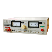
This Chapter gives descriptions and functions, connectors, switches, etc., for front and rear panels.
5.1 Description of Front Panel Items
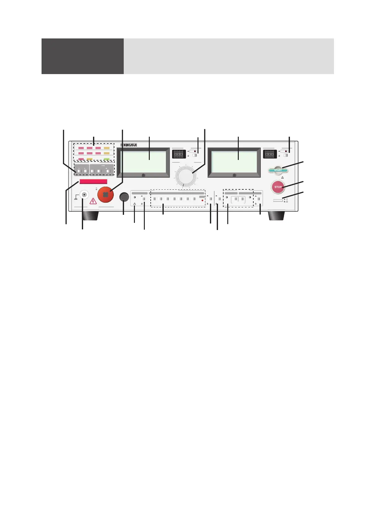
Fig.5-1
[1] POWER
|
/
○
Main power switch of Tester. Before turning on the switch, be sure to read Chapter 2 "WARNINGS
AND CAUTIONS FOR OPERATING THE TESTER" The state which this button was put is on
(1).
[2] STOP
Push this switch in case of following three.
• To cutoff the H.V output when in test operation.
• Reset from the FAIL alarm state.
•Reset from the PROTECTION state.
[3] START
As you press the switch when the Tester is in the RESET state, the DANGER lamp illuminates and
the test as selected by the FUNCTION selector switch is performed.
[4] UPPER ON/OFF
The switch selects whether the high-limit PASS-FAIL judgment in the insulation resistance test is
to be done or not.
[5] REFERENCE SET
The switches are for setting a PASS-FAIL judgement reference value for insulation resistance test.
When neither the UPPER switch nor the LOWER switch is pressed, the ohmmeter indicates the
value of measuring resistance.
When the LOWER switch is pressed, the ohmmeter indicates the low limit reference value for
PASS-FAIL judgment; when UPPER switch is pressed, the ohmmeter indicates the high limit refer-
ence value. When both switches are pressed, the LOWER switch has a priority. The limit reference
values are adjustable with the potentiometers located at right and left of the switches.
AUTO
MANUAL
IR
ACW ACW
IR AC W IR
TIMER
OFF
ON
ADD
LOWER UPPER
P
E
S
5
0
1
2
2
-
2
UPPER
LOWER
OUTPUT
INSULATION RESISTANCE
WITHSTANDING VOLTAGE
REMOTE
ACW FAIL
AUTO
TEST
PROTECTION
PASS
IR FAIL
500V
1000V
2.5kV 5kV
FUNCTION
REFERENCE
OFF
ON
CUTOFF CURRE NT
(
mA
)
LOW
5kV
1kV
MAX
HIGH VOLTAGE
MAX
0
TEST VOLTAGE
AC WI THSTA NDING VOLTAGE I
NSULATION RESISTANCE TESTER
TO
S
8870A
S
TIMER
S
TIMER
/
P
E
S
5
0
1
2
2
-
1
1000V
RANGE
500V
REFERENCE
OFF
ON
REFERENCE
80.5 1 2 4 10 100
5kV
RANGE
2.5kV
x0.1
x1 x1
x0.1
P
E
S
5
0
1
2
2
-
4
POWER
DANGER
9 9 99 9 9
[2] STOP
[1] POWER
│/○
[3] START
[11] REMOTE
[8] CUTOFF CURRENT
[10] LOWER REFERENCE
[9] LOWER ON/OFF
[19] TEST VOLTAGE
[7] RANGE 2.5kV/5kV
[13] DANGER
[6] RANGE 500/1000V
[16] OUTPUT HIGH VOLTAGE
[5] REFERENCE SET
[12] OUTPUT LOW
[4] UPPER
ON/OFF
[20] OHMMETER
[21] TIMER
[17] VOLTMETER
[18] TIMER
[15] INDICATOR LAMPS
[14] FUNCTION
+
-
+
-
+
-
+
-
+
-
+
-


 To Next Page