12 742.892 | 11.50
EN
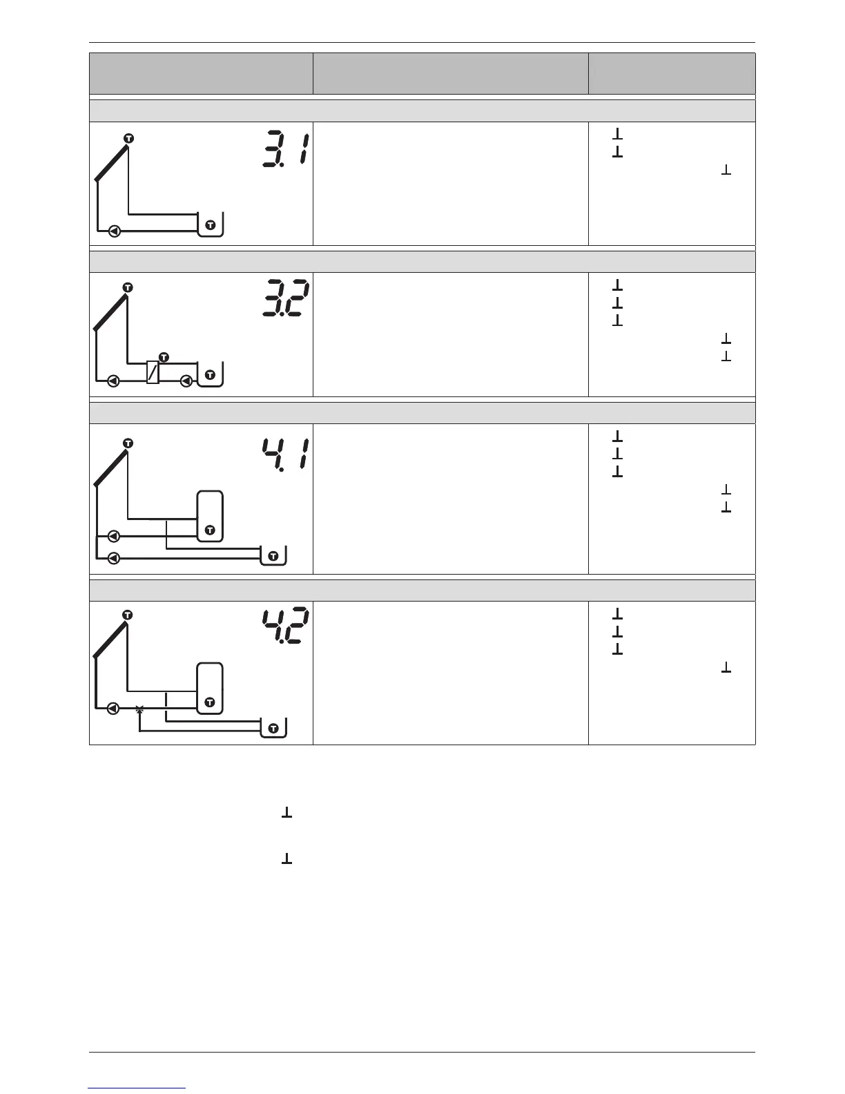
Display Legend Terminal layout
1 swimming pool, 1 collector array
R2
T1
T2
T1: Collector array sensor
T2: Swimming pool sensor
R2: Solar circuit pump
1,
2,
R2, N, PE (PWM R2,
2)
)
1 swimming pool with external heat exchanger, 1 collector array
R1
R2
T1
T2
T3
T1: Collector array sensor
T2: Swimming pool sensor
T3: External heat exchanger sensor
R1: Solar circuit pump
R2: Swimming pool loading circuit pump
1,
2,
3,
R1, N, PE (PWM R1,
1)
)
R2, N, PE (PWM R2,
2)
)
1 storage tank, 1 swimming pool, 1 collector array (pump-controlled)
T1
T2
T3
R1
R2
T1: Collector array sensor
T2: Lower storage tank sensor
T3: Swimming pool sensor
R1: Storage tank solar circuit pump
R2: Swimming pool solar circuit pump
1,
2,
3,
R1, N, PE (PWM R1,
1)
)
R2, N, PE (PWM R2,
2)
)
1 storage tank, 1 swimming pool, 1 collector array (pump/valve controlled)
R1
R2
T1
T2
T3
T1: Collector array sensor
T2: Lower storage tank sensor
T3: Swimming pool sensor
R1: Solar circuit pump
R2: Storage tank switching valve
6)
1,
2,
3,
R1, N, PE (PWM R1,
1)
)
R2, N, PE
Tab. 1: Terminal pin assignments
1)
Terminal pin assignments for PWM-controlled high-efficiency pumps: The power supply must be
connected to output R1 (N, PE), the control cable for the pump electronics must be connected
to PWM R1 and .
2)
Terminal pin assignments for PWM-controlled high-efficiency pumps: The power supply must be
connected to output R2 (N, PE), the control cable for the pump electronics must be connected
to PWM R2 and .
3)
Installation regulation: When no power is supplied to the switching valve then no flow occurs
through the storage tank.
4)
Installation regulation: When no power is supplied to the switching valve then the lower part of
the storage tank (T2) is loaded.
5)
Installation regulation: When no power is supplied to the switching valve then the first priority
storage tank (T2) is loaded.
6)
Installation regulation: When no power is supplied to the switching valve then the storage tank
(T2) is loaded.