10 742.892 | 11.50
EN
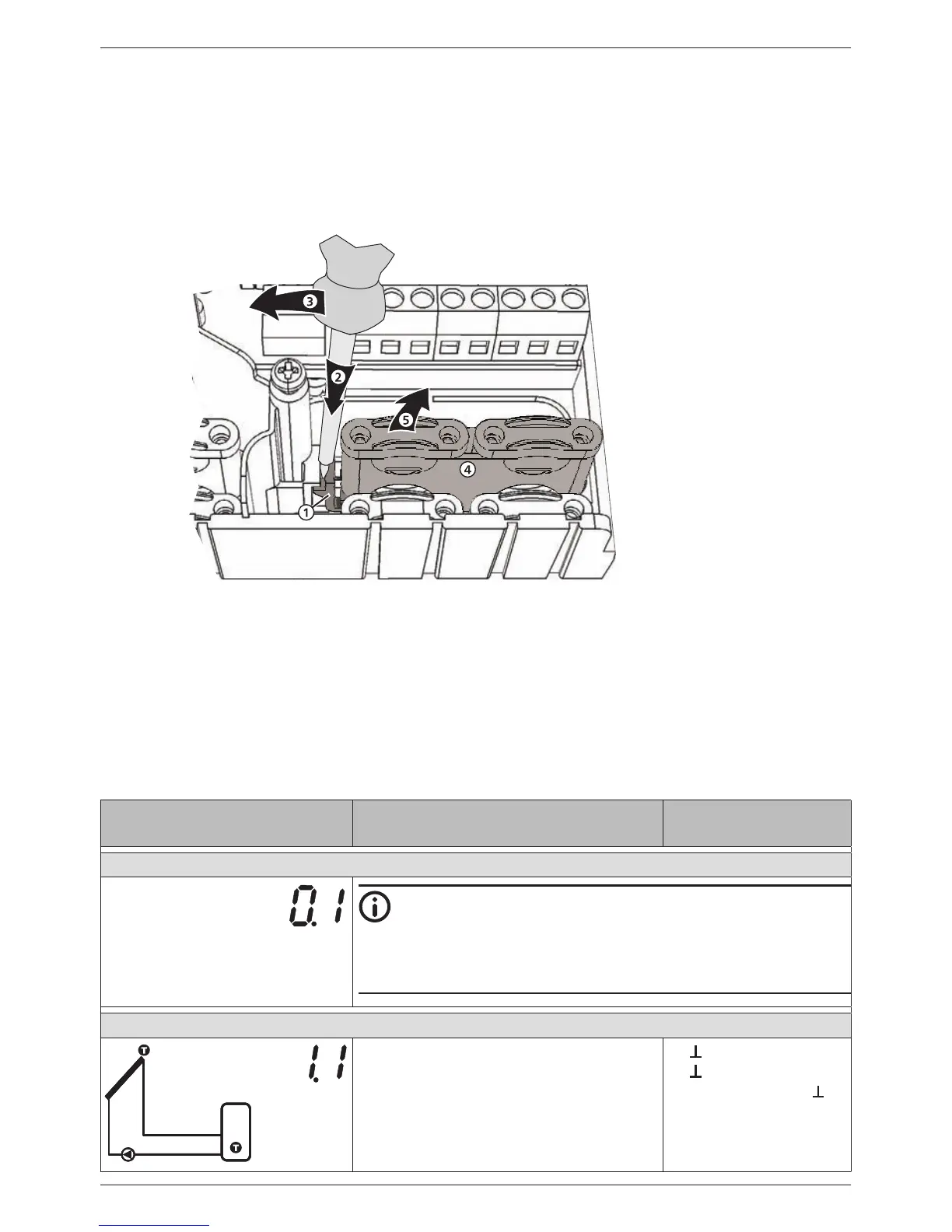
Remove the plastic links as follows:
1. Insert a flat-blade screwdriver under the right plastic link between the casing and
the spring clamp , (Fig. 5).
2. Carefully push the flat-blade screwdriver to the left . Lever the spring clamp to
the right until the plastic link is free.
3. Pull out the plastic link upwards by hand .
4. Remove the left plastic link accordingly.
Fig. 5: Removing the right plastic link
3.4 Terminal pin assignments
For each solar system that can be selected at the controller, the external components
(pumps, valves, temperature sensors) must be connected to particular terminals. The
following table provides information on this:
• Graphic and number of the solar system on the controller display. The graphic is only
intended to provide an overview and is not a technical drawing.
• Terminal pin assignments of the connected components
Display Legend Terminal layout
No system
Note
No system is used when only the functions are used. When
No system is selected then all inputs and outputs are freely
available for use by the functions. More information on this
is provided in Section 9, p. 28.
1 storage tank, 1 collector array
T1
T2
R1
T1: Collector array sensor
T2: Lower storage tank sensor
R1: Solar circuit pump
1,
2,
R1, N, PE (PWM R1,
1)
)